


4-16
STANDARD ACCESSORIES
Chip Conveyor
The chip conveyor is designed to bring chips out during
cutting.
When the hydraulic system is on, adjust the pressure control
valve to adjust the conveying speed.
Conveyor modes:
1.
Up: Chip conveyor conveys in reverse direction. Use
this mode to clear away jammed chips.
2.
Middle: Chip conveyor stops.
3.
Down: Chip conveyor conveys in normal direction.
Blade Tension Device
This blade tension device equipped with hydraulic
cylinder provides appropriate tension to the saw
blade.
To adjust blade tension, follow these steps:
1.
Unclamp carbide inserts (via HMI touch panel)
2.
Turn the blade tension selector handle to “relaxed
mode.”
3.
After replacing the blade, tighten the blade by
turning the blade tension selector.
Inverter
This inverter is installed inside the electrical compartment. It
is used to control and stabilize the saw blade speed during
cutting.
To adjust blade speed, use the
blade speed control
buttons
on the HMI screen.
Voltage used should not exceed AC 460V.
Note:
1.
Make sure the terminal points are connected.
2.
Make sure the ambient temperature is within
acceptable range and keep the surroundings well
ventilated.
3.
Keep the inverter away from dust.
4.
For repair or maintenance, please contact your local
agent.
Pressure control
valve & meter
Conveyor mode
stick shift
C
C
o
o
n
n
v
v
e
e
y
y
i
i
n
n
g
g
d
d
i
i
r
r
e
e
c
c
t
t
i
i
o
o
n
n
Blade tension
selector
Inverter
Summary of Contents for SVT-6070H
Page 2: ... ...
Page 4: ... ...
Page 10: ... ...
Page 15: ...1 5 Illustration Emergency Stop Emergency Stop ...
Page 20: ...1 10 Illustration Safety Labels ...
Page 25: ...2 3 MACHINE PARTS IDENTIFICATION ...
Page 26: ...2 4 FLOOR PLAN Machine top view Machine side view ...
Page 36: ... ...
Page 60: ... ...
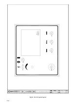
Page 62: ...5 2 Fig 5 1 Control panel layout ...
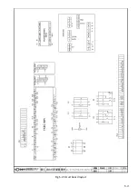
Page 63: ...5 3 Fig 5 2 Circuit board layout ...
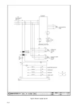
Page 64: ...5 4 Fig 5 3 Power supply layout ...
Page 65: ...5 5 Fig 5 4 PLC I O layout ...
Page 66: ... ...
Page 67: ...6 1 Section 6 HYDRAULIC SYSTEM HYDRAULIC DIAGRAM ...
Page 68: ...6 2 Fig 6 1 Hydraulic layout ...
Page 104: ... ...
Page 105: ... ...


