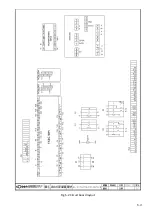


8-5
Gear Oil & Grease Injection Hole
:
1.
A grease injection hole and a gear oil injection
hole on the top of gear reducer.
: The position of injection indicating.
2.
Recommend keeping the volume over 50% inside
the vessel of volume window.
。
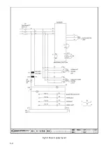
To unload the waste fluid:
Bottom of Gear reducer
1.
Put the waste oil container in the bottom of the
reducer for unloading waste fluid
.
2.
Use the wrench to open the screw for unloading the
waste fluid.
3.
Make sure the screw bolted tightly after unloading
completed,
STORAGE CONDITIONS
Generally, this machine will be stored on the following conditions in future:
(1) Turn off the power.
(2) Ambient temperature: 5
℃
~ 40
℃
(3) Relative humidity: 30%~
85%
(without condensation)
(4) Atmosphere: use a plastic canvas to cover machine to avoid excessive dust, acid fume,
corrosive gases and salt.
(5) Avoid exposing to direct sunlight or heat rays which can change the environmental
temperature.
(6) Avoid exposing to abnormal vibration.
(7) Must be connected to earth.
Gear Oil Injection Hole
Volume window
Grease Injection Nozzle
The Screw
Summary of Contents for SVT-6070H
Page 2: ... ...
Page 4: ... ...
Page 10: ... ...
Page 15: ...1 5 Illustration Emergency Stop Emergency Stop ...
Page 20: ...1 10 Illustration Safety Labels ...
Page 25: ...2 3 MACHINE PARTS IDENTIFICATION ...
Page 26: ...2 4 FLOOR PLAN Machine top view Machine side view ...
Page 36: ... ...
Page 60: ... ...
Page 62: ...5 2 Fig 5 1 Control panel layout ...
Page 63: ...5 3 Fig 5 2 Circuit board layout ...
Page 64: ...5 4 Fig 5 3 Power supply layout ...
Page 65: ...5 5 Fig 5 4 PLC I O layout ...
Page 66: ... ...
Page 67: ...6 1 Section 6 HYDRAULIC SYSTEM HYDRAULIC DIAGRAM ...
Page 68: ...6 2 Fig 6 1 Hydraulic layout ...
Page 104: ... ...
Page 105: ... ...


