


7-2
INTRODUCTION
1.
TPI: The number of teeth per inch as
measured from gullet to gullet.
2. Tooth Rake Angle: The angle of the tooth face measured with respect to a line perpendicular to the cutting
direction of the saw.
3.Tooth Pitch: Tooth pitch refers to the number of teeth per inch (tpi). 1 inch equates to 25.4 mm.
A distinction is made between constant tooth pitches with a uniform tooth distance, 2 tpi for example, and
variable tooth pitches with different tooth distances within one toothing interval.
Variable tooth pitches, for instance 2-3 tpi, can be characterized by two measures: 2 tpi stands for the maximum
tooth distance and 3 tpi stands for the minimum tooth distance in the toothing interval.
Constant
Variable
Min. Max
4. Set: The bending of teeth to right or left to allow clearance of the back of the blade through the cut.
5. Width: The nominal dimension of a saw blade as measured from the tip of the tooth to the back of the band.
6. Thickness: The dimension from side to side on the blade.
7. Gullet: The curved area at the base of the tooth. The tooth tip to the bottom of the gullet is the gullet depth.
SAW BLADE SELECTION
1. Band length
The dimensions of the band will depend on the band saw machine that has been installed.
Please refer to Section 2 – General Information
2. Band width
Band width: the wider the band saw blade, the more stability it will have.
3. Cutting edge material
The machinability of the material to be cut determines what cutting material you should choose.
7
Summary of Contents for SVT-6070H
Page 2: ... ...
Page 4: ... ...
Page 10: ... ...
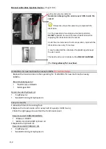
Page 15: ...1 5 Illustration Emergency Stop Emergency Stop ...
Page 20: ...1 10 Illustration Safety Labels ...
Page 25: ...2 3 MACHINE PARTS IDENTIFICATION ...
Page 26: ...2 4 FLOOR PLAN Machine top view Machine side view ...
Page 36: ... ...
Page 60: ... ...
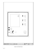
Page 62: ...5 2 Fig 5 1 Control panel layout ...
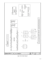
Page 63: ...5 3 Fig 5 2 Circuit board layout ...
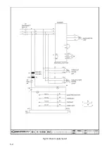
Page 64: ...5 4 Fig 5 3 Power supply layout ...
Page 65: ...5 5 Fig 5 4 PLC I O layout ...
Page 66: ... ...
Page 67: ...6 1 Section 6 HYDRAULIC SYSTEM HYDRAULIC DIAGRAM ...
Page 68: ...6 2 Fig 6 1 Hydraulic layout ...
Page 104: ... ...
Page 105: ... ...


