


1-1
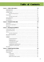
Section 1
SAFETY
INFORMATION
SAFETY INSTRUCTIONS
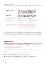
SAFEGUARD DEVICES
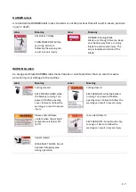
EMERGENCY STOP
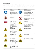
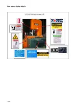
SAFETY LABELS
HEARING PROTECTION
CE COMPLIANCE
RISK ASSESSMENT
Safety is a combination of a well-designed machine, operator’s knowledge about the machine and
alertness at all times. COSEN’s band machine has incorporated many safety measures during the
design process and used protective devices to prevent personal injuries and potential risks. Warning
labels also serve as a reminder to the operator.
Throughout this manual, you will also see various safety-related symbols indicating
important
information that you should take note of prior to use of the machine or part of its functions.
These
important safety instructions do not cover all possible situations that might occur. It is your
responsibility to
take caution
and follow procedures stated in this manual when installing,
maintaining and operating your machine. Cosen will not be liable for damages resulting from
improper use.
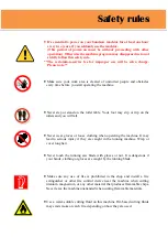
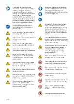
SAFETY INSTRUCTIONS
What the icons and signs in this user manual mean:
This icon marks
WARNING
; hazards or unsafe practices that may result in
personal injury or damage to the machine.
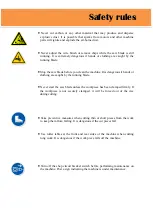
Supplementary information to the procedures described in this manual.
Call your local agent or our service center for help.
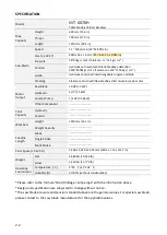
Summary of Contents for SVT-6070H
Page 2: ... ...
Page 4: ... ...
Page 10: ... ...
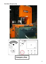
Page 15: ...1 5 Illustration Emergency Stop Emergency Stop ...
Page 20: ...1 10 Illustration Safety Labels ...
Page 25: ...2 3 MACHINE PARTS IDENTIFICATION ...
Page 26: ...2 4 FLOOR PLAN Machine top view Machine side view ...
Page 36: ... ...
Page 60: ... ...
Page 62: ...5 2 Fig 5 1 Control panel layout ...
Page 63: ...5 3 Fig 5 2 Circuit board layout ...
Page 64: ...5 4 Fig 5 3 Power supply layout ...
Page 65: ...5 5 Fig 5 4 PLC I O layout ...
Page 66: ... ...
Page 67: ...6 1 Section 6 HYDRAULIC SYSTEM HYDRAULIC DIAGRAM ...
Page 68: ...6 2 Fig 6 1 Hydraulic layout ...
Page 104: ... ...
Page 105: ... ...


