


4-6
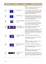
Stop cutting for single feeding mode and repeat feeding mode: During cutting, press this button
to stop the running blade. The workbed will also move slightly away from the blade in order to
protect the blade.
8.
HMI touch screen
Please refer to later section for detailed introduction.
9.
Cutting pressure control knob
This pressure control knob is used to adjust the cutting pressure of the blade.
Turning the knob clockwise increases the cutting pressure.
To obtain a good cutting result, choose the right cutting pressure by turning the knob until it
points to your material on the color chart.
10.
Cutting pressure meter
The cutting pressure indicates the current cutting pressure of the blade onto the material. Figures
show on the cutting pressure meter only when the blade has been started.
11.
Workbed feed speed control knob
This knob is used to adjust the feed speed of the workbed.
Turning the knob clockwise increases the feed speed.
Feed speed is a determining factor to a good cutting time and quality cutoff surface.
Set the feed speed in accordance with the cutting pressure control knob.
Also commonly known as the flow control valve.
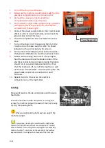
Human-machine-interface (HMI) touch screen
This HMI touch screen displays operation messages so that the operator is able to understand the
system condition. It also provides different operating modes and selections for the operator to work
with. During a cutting job, the operator can still enter the system and make changes to the cutting
operation as needed.
Do not wipe or clean the screen with volatile solvents.
Do not overexert pressure on the screen. The touch screen is very sensitive; all buttons on the
screen just need a slight touch to operate.
All range parameters in HMI are configured under the “manual” mode.
Summary of Contents for SVT-6070H
Page 2: ... ...
Page 4: ... ...
Page 10: ... ...
Page 15: ...1 5 Illustration Emergency Stop Emergency Stop ...
Page 20: ...1 10 Illustration Safety Labels ...
Page 25: ...2 3 MACHINE PARTS IDENTIFICATION ...
Page 26: ...2 4 FLOOR PLAN Machine top view Machine side view ...
Page 36: ... ...
Page 60: ... ...
Page 62: ...5 2 Fig 5 1 Control panel layout ...
Page 63: ...5 3 Fig 5 2 Circuit board layout ...
Page 64: ...5 4 Fig 5 3 Power supply layout ...
Page 65: ...5 5 Fig 5 4 PLC I O layout ...
Page 66: ... ...
Page 67: ...6 1 Section 6 HYDRAULIC SYSTEM HYDRAULIC DIAGRAM ...
Page 68: ...6 2 Fig 6 1 Hydraulic layout ...
Page 104: ... ...
Page 105: ... ...


