


4-5
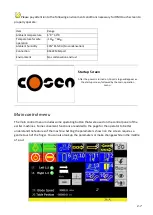
Control Buttons
1.
Emergency stop button
Press this button to stop the machine in an emergency. When the button is pressed, it brings the
machine to a full stop. The button locks when pressed. In order to unlock it, please turn the button
clockwise.
2.
Blade speed control knob (moved into HMI)
Blade speed is controlled by the inverter. Turning the knob clockwise increases the blade speed.
3.
Power indicator lamp
When the lamp is on, it indicates the power to the machine is turned on.
4.
Setting/cutting mode switch
This selector switch provides two modes to choose from: setting and cutting. To switch between
these modes, a key is required. Please keep the key at a safe place and do not lose it.
Turn this key switch to the left, the setting mode provides a safe environment while adjustment prior
to cutting is conducted or when machine maintenance is required. Cutting is not allowed in the
setting mode. Turn this key switch to the right, cutting is allowed only in cutting mode.
5.
Workbed to the left
Press and hold this button to move the workbed to the left. The workbed will continue moving until
the operator lets go of the button.
6.
Cutting start button
After starting the blade, press this button for the workbed to start feeding to the left. When starting
cutting and during cutting, please make sure cutting pressure and workbed feed speed are adjusted
properly according to your material. Under manual feeding mode, when letting go the cutting start
button, workbed stops immediately but the blade continues running. Under single feeding mode,
when cutting finishes, both workbed and blade stops at the preset cutting length position. Under
repeat feeding mode, when cutting finishes, both workbed and blade stops at the preset retract point.
7.
Workbed to the right
Use this button to feed the workbed to the right to your desired position:
When workbed is at retract point’s left and this button is pressed for more than 3 seconds,
workbed moves to the right to the retract point.
When workbed is at retract point’s right and this button is pressed for more than 3 seconds,
workbed moves to the right to the right limit switch.
When this button is pressed for less than 3 seconds, the workbed stops moving immediately
when operator lets go the button.
Summary of Contents for SVT-6070H
Page 2: ... ...
Page 4: ... ...
Page 10: ... ...
Page 15: ...1 5 Illustration Emergency Stop Emergency Stop ...
Page 20: ...1 10 Illustration Safety Labels ...
Page 25: ...2 3 MACHINE PARTS IDENTIFICATION ...
Page 26: ...2 4 FLOOR PLAN Machine top view Machine side view ...
Page 36: ... ...
Page 60: ... ...
Page 62: ...5 2 Fig 5 1 Control panel layout ...
Page 63: ...5 3 Fig 5 2 Circuit board layout ...
Page 64: ...5 4 Fig 5 3 Power supply layout ...
Page 65: ...5 5 Fig 5 4 PLC I O layout ...
Page 66: ... ...
Page 67: ...6 1 Section 6 HYDRAULIC SYSTEM HYDRAULIC DIAGRAM ...
Page 68: ...6 2 Fig 6 1 Hydraulic layout ...
Page 104: ... ...
Page 105: ... ...


