


4-3
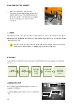
BEFORE OPERATING
Choosing an appropriate saw blade and using the right cutting method is essential to your cutting
efficiency and safety. Select a suitable saw blade and cutting method based on your work material
and job requirements e.g. cutting accuracy, cutting speed, economic concern, and safety control.
Wet cutting
If you choose dry cutting or low-speed cutting, the chips may accumulate in machine parts and may
cause operation failure or insulation malfunction. We suggest you choose wet cutting to avoid
machine damage.
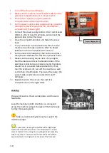
Cutting unknown materials
Before cutting an unknown material, consult the material supplier, burn a small amount of chips from
the material in a safe place, or follow any other procedure to check if the material is flammable.
Never take your eyes off the machine while in operation.
Cutting fluid
For cooling and lubrication purpose, we recommend you use water-soluble cutting fluids. The
following table lists out its pros and cons for your reference.
Pro
Con
Have a high cooling effect
Not flammable
Economical
Does not require cleaning of the cut
products
Remove machine paint
Lose its rust protection effect if
deteriorated
Tend to create foam
Subject to decay
Decline in performance, depending on
the quality of the water used for
dilution
Never use water as your coolant.
Always add coolant into water for better mix result.
Consult your coolant supplier for bandsaw use regarding coolant type and mix ratio.
Before starting a cutting job, make sure there is sufficient amount of coolant in the tank.
Check the fluid level through the sight gauge. Please refer to machine specifications in this
manual (Section 2) for tank capacity.
Summary of Contents for SVT-6070H
Page 2: ... ...
Page 4: ... ...
Page 10: ... ...
Page 15: ...1 5 Illustration Emergency Stop Emergency Stop ...
Page 20: ...1 10 Illustration Safety Labels ...
Page 25: ...2 3 MACHINE PARTS IDENTIFICATION ...
Page 26: ...2 4 FLOOR PLAN Machine top view Machine side view ...
Page 36: ... ...
Page 60: ... ...
Page 62: ...5 2 Fig 5 1 Control panel layout ...
Page 63: ...5 3 Fig 5 2 Circuit board layout ...
Page 64: ...5 4 Fig 5 3 Power supply layout ...
Page 65: ...5 5 Fig 5 4 PLC I O layout ...
Page 66: ... ...
Page 67: ...6 1 Section 6 HYDRAULIC SYSTEM HYDRAULIC DIAGRAM ...
Page 68: ...6 2 Fig 6 1 Hydraulic layout ...
Page 104: ... ...
Page 105: ... ...


