


4-4
CONTROL PANEL
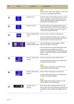
The control panel is located on the top of the electrical box. It includes the following function: power
system, hydraulic system, cooling system, the human-machine–interface (HMI) and the projecting
light system. The operator must fully understand the function of each switch and button before
operating the machine.
No.
Control Function
No.
Control Function
1 Emergency stop button
7 Workbed to the right button
2 Blade speed control knob (moved into
HMI)
8 HMI touch screen
3 Power indicator lamp
9 Cutting pressure control knob
4 Cutting safety key switch
10 Cutting pressure meter
5 Workbed to the left button
11 Workbed feed speed control knob
6 Cutting start button
Summary of Contents for SVT-6070H
Page 2: ... ...
Page 4: ... ...
Page 10: ... ...
Page 15: ...1 5 Illustration Emergency Stop Emergency Stop ...
Page 20: ...1 10 Illustration Safety Labels ...
Page 25: ...2 3 MACHINE PARTS IDENTIFICATION ...
Page 26: ...2 4 FLOOR PLAN Machine top view Machine side view ...
Page 36: ... ...
Page 60: ... ...
Page 62: ...5 2 Fig 5 1 Control panel layout ...
Page 63: ...5 3 Fig 5 2 Circuit board layout ...
Page 64: ...5 4 Fig 5 3 Power supply layout ...
Page 65: ...5 5 Fig 5 4 PLC I O layout ...
Page 66: ... ...
Page 67: ...6 1 Section 6 HYDRAULIC SYSTEM HYDRAULIC DIAGRAM ...
Page 68: ...6 2 Fig 6 1 Hydraulic layout ...
Page 104: ... ...
Page 105: ... ...


