


4-9
No
Item
Function
Description
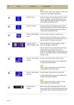
blade, press saw blade stop button.
Before starting the saw blade, please
choose the feeding mode first. Once the saw
blade is running, the saw blade needs to be
stopped to be able to switch the feeding mode.
8
Single feeding mode
Press this button to switch to the single feeding
mode. The green solid line indicates the single
feeding has been turned on.
Press the “saw blade start” button (#3 in HMI) to
start the blade. At this time, the table will not
start feeding yet. Press the “cutting start” button
(#5 on the control panel) to start feeding the
workbed. The workbed will continue feeding
until the saw blade has cut the preset cutting
length, at which point, cutting will be completed,
the blade will stop and the workbed will remain
at the same position.
To stop cutting, press “saw blade stop”
button to stop the saw blade or press “workbed
to the right” button to stop the saw blade and
the workbed.
9
Repeat feeding mode Press this icon to switch to the repeat feeding
mode. The green solid line indicates the repeat
feeding mode has been turned on.
Press the “saw blade start” button (#3 in HMI) to
start the blade. At this time, the table will not
start feeding yet. Press the “cutting start” button
(#5 on the control panel) to start feeding the
workbed. The workbed will continue feeding
until reaching the left limit switch, at which
point, cutting will be completed, the blade will
stop and the workbed will return back to the
retract point. (Refer to Worklength selector
under Standard Accessories.)
To stop cutting, press “saw blade stop”
button to stop the saw blade or press “workbed
to the right” button to stop the saw blade and
the workbed.
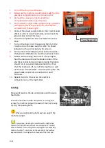
10
Laser light ON/OFF
Press this button to turn on the laser light. A
beam
of light will be projected on the work piece for
alignment.
A solid yellow light bulb icon indicates the lamp
has been turned on.
Summary of Contents for SVT-6070H
Page 2: ... ...
Page 4: ... ...
Page 10: ... ...
Page 15: ...1 5 Illustration Emergency Stop Emergency Stop ...
Page 20: ...1 10 Illustration Safety Labels ...
Page 25: ...2 3 MACHINE PARTS IDENTIFICATION ...
Page 26: ...2 4 FLOOR PLAN Machine top view Machine side view ...
Page 36: ... ...
Page 60: ... ...
Page 62: ...5 2 Fig 5 1 Control panel layout ...
Page 63: ...5 3 Fig 5 2 Circuit board layout ...
Page 64: ...5 4 Fig 5 3 Power supply layout ...
Page 65: ...5 5 Fig 5 4 PLC I O layout ...
Page 66: ... ...
Page 67: ...6 1 Section 6 HYDRAULIC SYSTEM HYDRAULIC DIAGRAM ...
Page 68: ...6 2 Fig 6 1 Hydraulic layout ...
Page 104: ... ...
Page 105: ... ...


