Standard Practices
Teledyne Continental Motors, Inc.
TM
C-22
IOF-240 Series Engine Maintenance Manual
29 November 2006
C-12.
Harness Routing
Procedure
1.
Inspect all proposed harness routes. Consider normal movement and relative motion
of the various engine or aircraft parts that will be attached to the harness.
2.
Route the manifold pressure, manifold temperature, fuel pressure, and speed sensor
channels separately to ensure signal integrity.
3.
Do not route harnesses near belts or pulleys without the use of belt guards; belt failure
may damage the wiring harness.
4.
Do not secure wiring harnesses to fuel lines.
5.
Use existing baffle supports and brackets wherever practical to support the harness.
6.
Secure harnesses to minimize the possibility of chafing, vibration, and excessive heat
exposure. The maximum operating temperature for the low-voltage harness is 300°F
(149
°
C), the low-voltage harness must not come in contact with a surface hotter than
250
°
F (121
°
C).
1)
Gather the leads of the harness together; use cable ties to “stalk” the various
sections of the harness
2)
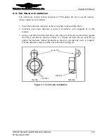
Secure the harness “stalks” to the engine and airframe. Refer to Figure C-13.
The butterfly technique is the preferred method for securing the harness to the
aircraft/engine structure with cable ties. This technique involves using two
cable ties; one passing around the harness section and the securing structure
and the other wrapping around and perpendicular to the path of the first at a
point between the harness section and the securing structure.
3)
The largest allowable unsecured segment along any engine wiring harness is 8
inches (20.32 cm).
Figure C-13.
Secure a Harness to Existing Wiring Bundles
7.
Route the wiring harnesses through baffles where necessary. All baffle penetrations
by a harness must be lined with a suitable grommet to prevent damage.
8.
Inspect installation and correct any discrepancies.


