Standard Practices
Teledyne Continental Motors, Inc.
TM
C-12
IOF-240 Series Engine Maintenance Manual
29 November 2006
C-6.2. Helical Coil Insertion
Procedure
1.
Blow all debris and liquid out of the tapped hole.
2.
Use a proper size installation tool and slide the new helical coil insert over the slotted
end of the driving mandrel of the tool.
3.
Engage the driving tang (bent end) of the helical coil in the mandrel slot.
4.
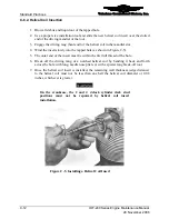
Wind the insert slowly into the tapped hole (as shown in Figure C-5).
5.
The outer end of the insert must lie within the first full thread of the hole.
6.
Break off the driving tang of a notched helical coil by bending it back and forth
across the hole with long, needle nose pliers or with a special tang break-off tool.
7.
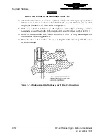
Once the helical coil insert is installed, the remaining wall thickness (edge distance)
to the helical coil must not be less than one half the helical coil diameter or 0.08
inches, whichever is greater.
WARNING
On the crankcase, the 2 and 4 o'clock cylinder deck stud
positions must not be repaired by helical coil insert
installation.
Figure C-5.
Installing a Helical Coil Insert


