Non-Overhaul Removal and Replacement
Teledyne Continental Motors, Inc.
TM
10-76
IOF-240 Series Engine Maintenance Manual
29 November 2006
7.
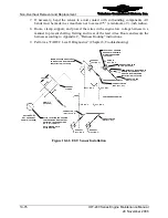
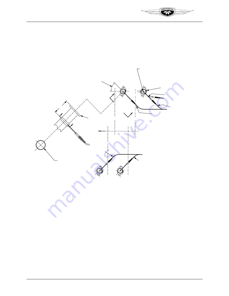
If necessary, bend the sensor to avoid contact with surrounding components. All
bends must be made in a smooth arc not to exceed 75
°
(a minimum of ½-inch radius).
8.
Route, clamp, support, and protect the wires in the engine low voltage harness in a
manner to prevent chafing, fretting, and wear of the lead wires. Route and secure the
harness according to Appendix C, “Harness Routing” instructions.
9.
Perform a “FADEC Level I Diagnostics” (Chapter 8, Troubleshooting).
W
W
THERMOCOUPLE ANGULARITY
TO BE SET FOR BEST AIRFRAME
INSTALLATION (4 PLACES)
C
L
C
L
C
L
C
L
C
L
C
L
C
L
C
L
EXHAUST
(CYL. NO. 3)
EXHAUST
(CYL. NO. 1)
EXHAUST
(CYL. NO. 4)
EXHAUST
(CYL. NO. 2)
CONNECTOR TAG
“EGT (CYL. # 4)”
CONNECTOR TAG
“EGT (CYL. # 2)”
CONNECTOR TAG
“EGT (CYL. # 2)”
CONNECTOR TAG
“EGT (CYL. # 2)”
Y
Y
LOCATE EGT PROBE IN
EXHAUST PIPE WITHIN
DIAMETER SPECIFIED
(4 PLACES)
TORQUE CLAMP 30-35
IN. LBS. (4 PLACES)
PERMISSIBLE TO MAKE SMOOTH
BEND IN EGT PROBE UP TO 75°
DEG. FOR BEST AIRFRAME
INSTALLATION (4 PLACES)
2.50 ± 0.25
CENTERLINE OF ENGINE
CYL. NO. 3
CYL. NO. 1
CYL. NO. 4
CYL. NO. 2
PROP
EXHAUST
FLANGE
VIEW
Y-Y
(4 PLACES)
SECTION
W-W
EGT PROBE NOT
SHOWN (4 PLACES)
AFTER LOCATING THE POSITION
FOR THE PROBE DRILL HOLE AT
SELECTED LOCATION USING A
NO. 17 (0.1730) DRILL
NOTE: DEBURR HOLE
AFTER DRILLING
Figure 10-62.
EGT Sensor Installation


