Teledyne Continental Motors, Inc.
TM
Non-Overhaul Removal and Replacement
IOF-240 Series Engine Maintenance Manual
10-55
31 August 2007
Change 1
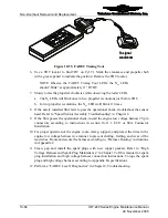
Figure 10-45.
Completed Splice
22.
Inspect the continuity of the sensor lead wires. If the inspection reveals poor
continuity readings and/or if any wire appears damaged, isolate the faulty wiring and
repeat the procedure.
23.
If splice was for wire repair, proceed to step 24. If sensor was removed for
replacement, locate the appropriate reference below to install the sensor.
a.
Install the tagged CHT Sensor of the low voltage harness into the respective
cylinder head using the bayonet adapters. Insert the CHT probe into the bayonet
adapter against the spring force and twist it to lock it in place. Verify the CHT
sensor is securely installed in bayonet adapter.
WARNING
Failure to install the CHT Sensor on the correct cylinder will
result in abnormal engine operation
b.
Install the MAT sensors according to instructions in Section 10-11.17, “Manifold
Air Temperature (MAT) Sensor Installation.”
c.
Install the fuel injector solenoid according to Section 10-11.11, “Fuel Injection
Solenoid Installation.”
24.
If all lead wiring is intact, bundle the sensor leads as required. For proper operation of
the engine, route, clamp, support, and protect the wires in the low voltage harness in a
manner to prevent chafing, fretting, and wear of the lead wires. Route and secure the
harness according to the “Harness Routing” instructions in Appendix C.
CAUTION: Avoid making sharp bends or kinks in the lead wires.
25.
When maintenance is complete, perform a FADEC Level I Diagnostic according to
instructions in Chapter 8, Troubleshooting.


