Non-Overhaul Removal and Replacement
Teledyne Continental Motors, Inc.
TM
10-64
IOF-240 Series Engine Maintenance Manual
29 November 2006
4.
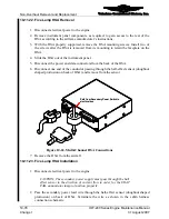
Cut, remove, and discard the cable ties from each 25-pin connector.
5.
Remove the safety wire from the 25-pin connector securing screws.
NOTE: The 25 pin connector fasteners are captive in the engine
low voltage harness connector backshell and cannot be removed.
6.
Loosen the two captive fasteners on each connector until fully disengaged from the
SSA.
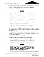
WARNING
Do not separate the connector from the SSA by pulling on the
harness leads. Pulling on the harness leads can cause
permanent, irreparable damage to the engine low voltage
harness which may result in engine malfunction.
7.
Remove the 25-pin connectors by firmly grasping the edges of the connector
backshell and pull the backshell away from the SSA.
8.
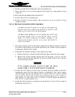
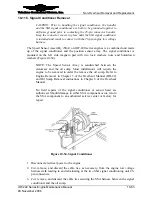
Refer to (Figure 10-54); remove and discard the EMI gaskets and environmental seals
from each connector.
9.
Place protective covers over each of the 25-pin connectors.
10.
Remove two sets of hold down washers, washers, and nuts from SSA signal
conditioner. Remove the SSA signal conditioner from the accessory case.
11.
Temporarily secure the SSA signal conditioner near the lower left engine mount with
a cable tie.
12.
Remove and discard the signal conditioner gasket from the accessory case.
13.
Drain the engine oil from the oil sump (Chapter 9, Engine Oil Servicing).
14.
Follow the “Engine Oil Sump Removal” instructions in Chapter 6 of the TCM
Overhaul Manual (OH-22).
15.
Cut the wire tie temporarily securing the SSA signal conditioner (installed earlier).
16.
Remove the SSA from the engine.
10-11.6. Signal Conditioner Installation
Procedure
1.
Disconnect electrical power to the engine.
2.
Clean the crankcase and accessory case SSA gasket sealing surfaces.
3.
Install the Speed Sensor Assembly along with the Oil Sump according to the “Oil
Sump Installation” instructions in Chapter 11 of the Overhaul Manual (OH-22)
4.
Fill the oil sump to the specified capacity (Chapter 9, “Engine Oil Servicing") and
install the oil gauge rod.
5.
Cut and remove the wire tie temporarily securing the SSA signal conditioner.
6.
Apply Gasket Maker to both sides of the signal conditioner gasket.
7.
Install the signal conditioner with a gasket on the left magneto drive pad.


