Teledyne Continental Motors, Inc.
TM
Non-Overhaul Removal and Replacement
IOF-240 Series Engine Maintenance Manual
10-63
29 November 2006
10-11.5. Signal Conditioner Removal
CAUTION: Prior to handling the signal conditioner, the handler
and the SSA signal conditioner are both to be grounded together to
airframe ground prior to contacting the 25-pin connector headers.
Keep the connector covers in place until the SSA signal conditioner
is installed and ready to connect with the 25-pin engine low voltage
harness.
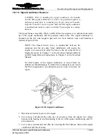
The Speed Sensor Assembly (SSA) on IOF-240 series engines is a combined unit made
up of the signal conditioner and the position sensor array. The signal conditioner is
mounted on the left side magneto pad with two lock washers, nuts, and hold-down
washers (Figure 10-54).
NOTE: The Speed Sensor Array is sandwiched between the
crankcase and the oil sump. Most installations will require the
engine to be removed in order the remove the oil sump. Refer to
Engine Removal in Chapter 5 of the Overhaul Manual (OH-22)
and Oil Sump Removal instructions in Chapter 6 of the Overhaul
Manual.
No field repairs of the signal conditioner or sensor head are
authorized. Should damage to either SSA component occur, return
the SSA component to an authorized service center or factory for
repair.
Figure 10-54.
Signal Conditioner
Procedure
1.
Disconnect electrical power to the engine.
2.
Cut, remove, and discard the cable ties, as necessary, from the engine low voltage
harness stalk leading to and terminating at the two SSA signal conditioning unit 25-
pin connectors.
3.
Cut, remove, and discard the cable ties securing the SSA harness between the signal
conditioner and the oil sump.


