Non-Overhaul Removal and Replacement
Teledyne Continental Motors, Inc.
TM
10-60
IOF-240 Series Engine Maintenance Manual
29 November 2006
5.
Measure continuity between newly installed ground strap and engine with DVM.
Resistance should not exceed 0.5 ohms.
6.
Perform a “FADEC Level I Diagnostics” in Chapter 8, Troubleshooting.
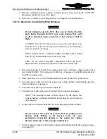
10-11.3. Electronic Control Unit (ECU) Removal
WARNING
Do not attempt to open the ECU. There are no field serviceable
parts inside. Opening the ECU may cause damage that could
result in abnormal engine operation or loss of power while in
flight.
CAUTION: Each ECU is shipped in a sealed, anti-static plastic bag.
Keep the ECU in the sealed bag until installation to prevent damage
from electrostatic discharge.
NOTE: Master Power Controller (MPC) and Electronic Control
Unit (ECU) nomenclature refer to the same unit.
There are no field serviceable components within the ECUs.
Should an ECU malfunction, replace it with a serviceable unit.
Procedure
1.
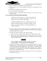
Disconnect electrical power to the engine and remove the high voltage ignition lead
wires from the ECU. Cut and remove cable ties as necessary to pull the leads clear of
the ECU mounting area.
2.
Place protective covers over the threaded end of each of the ECU spark towers.
3.
Cut and remove cable ties from the engine low voltage harness stalk leading up to the
50-pin connector as necessary.
4.
Cut and remove the 50-pin connector cable tie.
5.
Cut and remove the safety wire from the 50-pin connector fasteners.
NOTE: The securing screws are held captive by the engine low
voltage harness connector backshell and cannot be removed from
the connector.
6.
Loosen the two fasteners until they are fully disengaged from the ECU.
WARNING
Do not separate the connector from the ECU by pulling on the
harness leads. Pulling on the harness leads can cause
permanent, irreparable damage to the engine low voltage
harness which may result in engine malfunction.
7.
Firmly grasp the edges of the 50-pin connector backshell and pull the connector away
from the ECU.


