Teledyne Continental Motors, Inc.
TM
Non-Overhaul Removal and Replacement
IOF-240 Series Engine Maintenance Manual
10-37
29 November 2006
10.
Remove the ring compressor and push the cylinder assembly against the crankcase
cylinder deck with the stud holes aligned.
11.
While supporting the cylinder, install, but do not torque, the cylinder flange nuts (45
and 46).
12.
Torque the cylinder fastening hardware according to “Cylinder Torque” instructions.
13.
Lubricate the cleaned, serviceable hydraulic tappets with Dow-Corning G-N paste
and insert the tappets (cupped surface facing outward) in the holes from which they
were removed. Lubricate new tappets with Dow-Corning G-N paste and install the
new tappets in the remaining tappet bores.
14.
Install new spring (37) and new packing (39) on the push rod housing.
15.
Install the springs (39), washers (36), and push rod housing (35).
16.
Install the push rods (40) in their respective housings (35).
17.
Position the crankshaft so the piston is at top dead center and both intake and exhaust
valves of the cylinder are closed.
18.
Check the distance between the retainers and rocker arms with a feeler gage. Side
Clearance should be between 0.005 and 0.035.
FEELER GAUGE
0.005 - 0.035
FEELER GAUGE
0.005 - 0.035
Figure 10-19.
Rocker Arm Side Clearance
19.
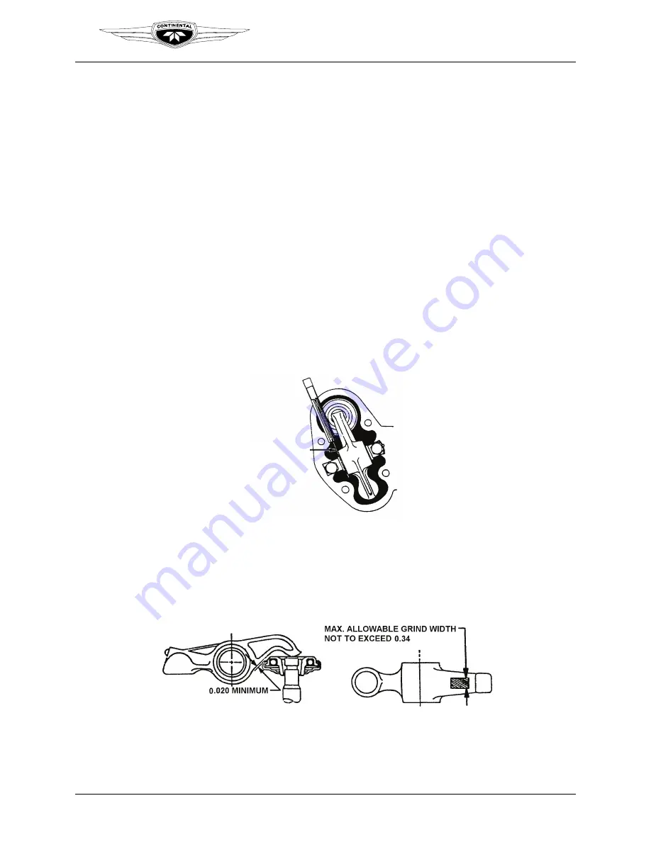
Install the rocker arms (20), valve rocker shafts (24), and thrust washers (23) on the
cylinder head, aligning them with the helical positions. Check rocker arm to rotocoil
clearance for 0.020 minimum clearance. Refer to Figure 10-20.
Figure 10-20.
Rocker Arm to Rotocoil Clearance
20.
If necessary, smoothly grind the underside of the rocker arm to gain the specified
minimum clearance according to “Machining the Rocker-Arm-to-Rotocoil
Clearance” in Chapter 9 of the TCM Overhaul Manual (OH-22).


