Non-Overhaul Removal and Replacement
Teledyne Continental Motors, Inc.
TM
10-72
IOF-240 Series Engine Maintenance Manual
29 November 2006
5.
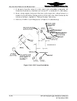
Use a DVM to measure the resistance between the connector body and airframe
electrical ground bus; resistance must be less than 0.5 ohms.
WARNING
If the resistance exceeds 0.5 ohms, there is a ground problem.
Correct the ground problem and recheck the resistance. Do not
return the aircraft to service until the resistance is less than 0.5
ohms.
6.
Connect the Engine Low Voltage Harness connector to the Fuel Pressure Sensor. To
connect, orient the alignment keys of the connector with those of the sensor. Push the
harness connector onto the sensor connector while turning clockwise until the
connector locking ring snaps to the locked position. When properly mated and locked,
the bayonet orientation pins are visible in the locking ring pin observation port.
7.
For proper operation of the engine, route, clamp, support, and protect the wires in the
Engine Low Voltage Harness in a manner to prevent chafing, fretting, and wear of the
lead wires. Route and secure the harness IAW Appendix C, “Harness Routing.”
8.
Set the aircraft Fuel Selector Valve to the ON position and activate the fuel boost
pump and leak check the fuel delivery system.
9.
Perform a “FADEC Level I Diagnostics” in Chapter 8, Troubleshooting.
WARNING
If the fuel pump, fuel distribution block, fuel pressure sensor
or fuel injectors are removed and replaced, the fuel system
must be checked and possibly adjusted in accordance with the
“Engine Operational Check” instructions in Chapter 6.
10.
Perform an engine operational check according to the instructions in Chapter 6,
Operational Performance Checks.


