


2-22
Compaq ServerNet II PCI Adapter and Switch Installation Guide
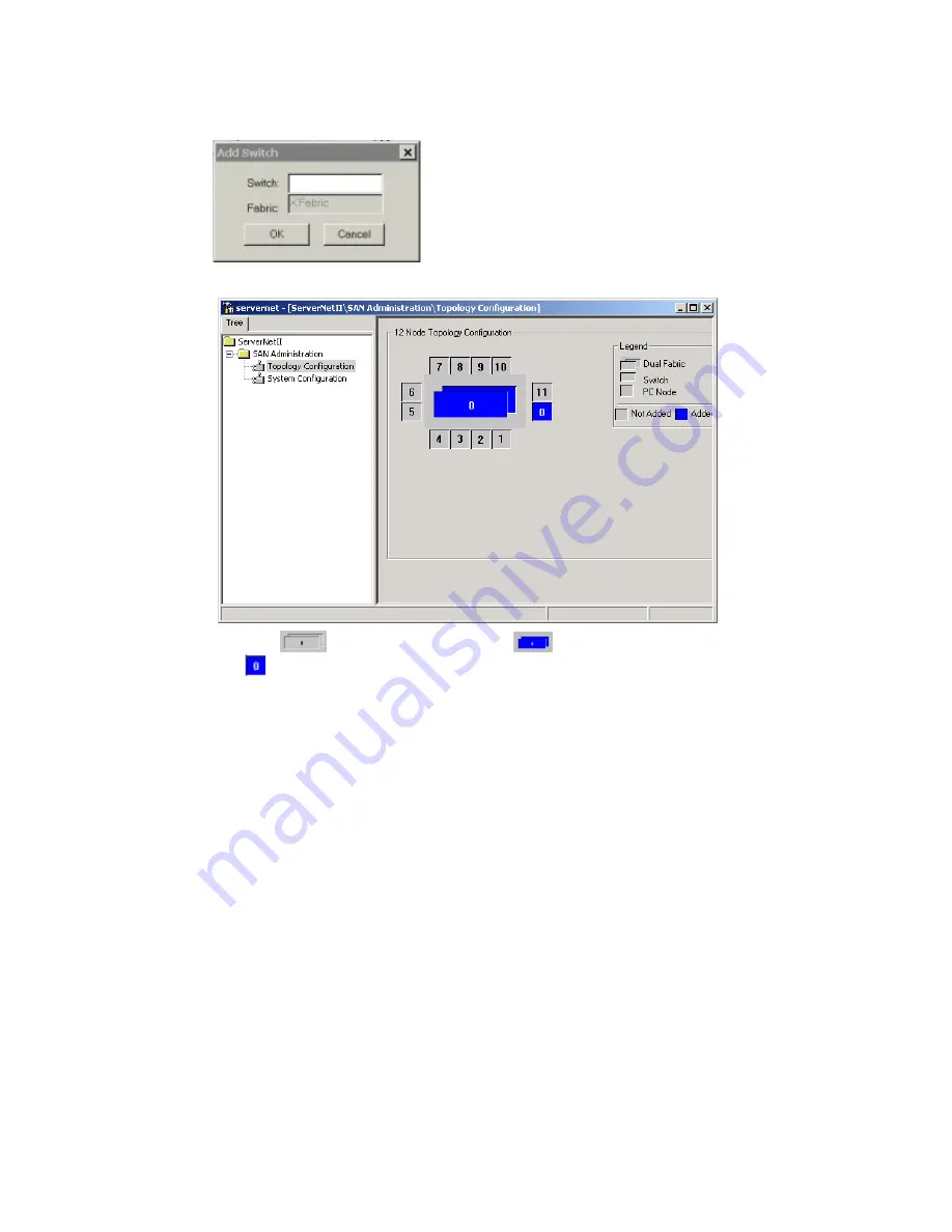
6.
Repeat Steps 3-5 to add the Y Switch.
NOTE:
The
representing the Switch turns blue
when you add the first Switch.
The
is the port on the primary node, which you added in previous steps.
7.
After you add both Switches, re-check the labels on the Switch cables:
a.
Ensure that the “X” Switch has a cable labeled “X” (from Adapter X port) and the
“Y” Switch has a cable labeled “Y” (from Adapter Y port). Do not mix fabrics. Since
there is only one node (the primary), this should be easy since there are only two
cables to connect. If these are correct, you should have a connection between the
primary node and the Switches.
b.
Check that the cables between the primary administrative node and the Switches are
numbered for the appropriate Switch. Do not mix cables between Switches.
c.
Check that the cable is connected to the Switch port that you selected when you
configured the primary node.
8.
Check the LEDs on the front of the Switches. The Link-Alive LED for the corresponding
Switch port should be green.
9.
From the primary administrative node, invoke and run diagnostics. See Chapter 3 “Using
Diagnostics” to start diagnostics. If a diagnostic test fails, see Appendix F, “ServerNet II
ServerNet II Troubleshooting” for any problems you may encounter.
10.
From the command line, ping the IP address of the primary administrative node (which is
the only node currently in the SAN topology).
If the checks in Steps 7-10 are OK, you can begin adding the end nodes (one at a time) to
the SAN topology. If these steps are not OK, see Appendix F, “ServerNet II ServerNet II
Troubleshooting.”