background image

System Functions: Upgrading Firmware

C-3

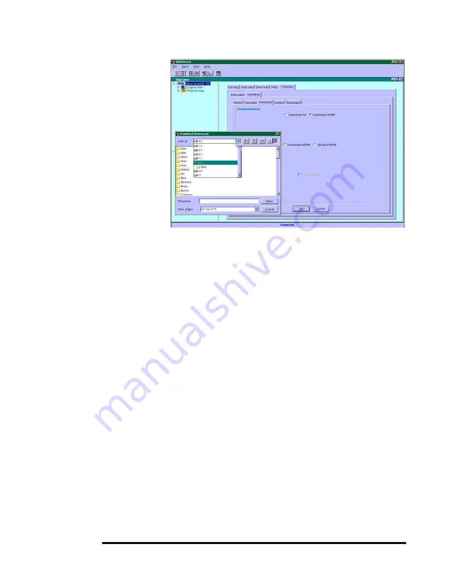
Upgrade Both Boot Record and Firmware Binaries

1. 

Connect to the RAID system locally or from a remote host using
RAIDWatch Manager.  While connected to the RAID system,
there will be icon(s) with IP address specified on the left of the
menu screen.  Select by double-clicking the icon of the RAID
system which firmware is to be upgraded.  Select the controller
icon and then select the “RAID system-to-host bus” (usually
appears as In-band SCSI).  Double-click the RAID-to-host-bus
to connect to the desired controller.  Choose the “RAID view”
icon on the controller panel or the RAID view icon on the
control bar.  The RAID view window will appear.  Choose
"Controller" > "Download" -> and click among the selections
"Download FW/BR” (Firmware and Boot Record).

2. 

Provide the boot record binary filename, the RAIDWatch
Manager will start to download the boot record binary to the
controller.

3. 

After the boot record download is completed, provide the
firmware filename to the RAIDWatch Manager. It will start to
download the firmware to the controller.

4. 

Shutdown the system which is accessing the RAID, then reset
the controller in order to use the new downloaded firmware.

With firmware release 3.21 and above

, host I/Os will not be

interrupted by the download process.  Users may find a chance
to stop host I/O and reset the controller for new firmware to
take effect.

Summary of Contents for External RAID Controller & Subsystem Infortrend

Page 1: ...Infortrend External RAID Controller Subsystem Generic Operation Manual Revision 1 61 Firmware Version 3 31...

Page 2: ...n First Published 2003 All rights reserved No part of this publication may be reproduced transmitted transcribed stored in a retrieval system or translated into any language or computer language in an...

Page 3: ...n the U S and other countries All other names brands products or services are trademarks or registered trademarks of their respective companies RMA Policy Please visit our websites www infortrend com...

Page 4: ...12 What is a logical volume 12 Spare drives assigned to a logical volume 14 Limitations 15 Partitioning partitioning the logical drive or partitioning the logical volume 15 Different write policies w...

Page 5: ...d Edit Event Logs 7 Chapter 5 LCD Keypad Operation 5 1 Power on RAID Enclosure 1 5 2 Caching Parameters 1 Optimization Modes 1 Optimization Mode and Stripe Size 2 Optimization for Random or Sequential...

Page 6: ...s Primary ID Drive Channel 27 Setting a SCSI Channel s Secondary ID Drive Channel 28 Setting Channel Bus Terminator 28 Setting Transfer Speed 29 Setting Transfer Width 30 Viewing and Editing SCSI Tar...

Page 7: ...e Capacity 6 Assign Spare Drives 7 Disk Reserved Space 7 Logical Drive Assignments 7 Write Policy 7 Initialization Mode 8 Stripe Size 8 7 5 Creating a Logical Volume 10 7 6 Partitioning a Logical Driv...

Page 8: ...port 32 Maximum Tag Count 32 Data Rate 32 7 13 System Functions 34 Mute Beeper 34 Change Password 34 Changing the Password 35 Setting a New Password 35 Disabling the Password 36 Reset Controller 36 Sh...

Page 9: ...ne Failing Drive 2 Replace after Clone 2 Perpetual Clone 3 9 1 2 S M A R T Self Monitoring Analysis and Reporting Technology 5 Configuration Procedure 7 Enabling the S M A R T Feature 7 Examining Whet...

Page 10: ...A Channel Bus 10 9 B Controller Failover and Failback 10 11 C Active to Active Configuration 10 11 D Traffic Distribution and Failover Process 10 12 Symptoms 10 13 Connection 10 13 10 2 Preparing Cont...

Page 11: ...hronization on Write Through 10 35 Chapter 11 Record of Settings 11 1 View and Edit Logical Drives 1 Logical Drive Information 1 Partition Information 2 11 2 View and Edit Logical Volumes 3 Logical Vo...

Page 12: ...4 Fibre Channel Support 5 S M A R T Support 6 Redundant Controller 6 Data Safety 7 System Security 8 Environment Management 9 SAF TE S E S support 9 User Interface 10 RAIDWatch on board 10 RS 232C Te...

Page 13: ...IP 3 6 NPC Onboard 3 9 Chapter 4 LCD Screen Messages Page number View and Edit Event Logs 4 7 Chapter 5 Chapter 7 Starting RAID via the LCD Panel Terminal Emulation Page number LCD Terminal Starting...

Page 14: ...els 5 25 7 25 Viewing and Re defining Channel Mode 5 25 7 25 Setting Channel ID Host Channel 5 26 7 26 Viewing channel ID 5 26 7 26 Adding a Channel ID 5 26 7 26 Deleting a Channel ID 5 27 7 27 Settin...

Page 15: ...ibre Loops 8 12 Multi host Access Control LUN Filtering 8 14 Creating LUN Masks 8 15 WWN Name List 8 16 Logical Unit to Host LUN Mapping 8 16 LUN Mask ID Range Configuration 8 18 Filter Type Include o...

Page 16: ...Configuration Using Manual Setting 10 21 Starting the Redundant Controllers 10 22 Creating Primary and Secondary IDs 10 22 Assigning a Logical Drive Logical Volume to the Secondary Controller 10 23 Ma...

Page 17: ...d RS 232 Firmware Download C 1 Redundant Controller Rolling Firmware Download C 1 Redundant Controller Firmware Sync version C 2 Upgrading Firmware Using In band SCSI RAIDWatch Manager C 2 Establish t...

Page 18: ...0 10 Table 10 2 ID Mapping Status Controller Failed 10 10 List of Figures Chapter 1 Figure 1 1 Logical Drive 1 1 Figure 1 2 NRAID 1 3 Figure 1 3 JBOD 1 3 Figure 1 4 RAID 0 1 4 Figure 1 5 RAID 1 1 4 Fi...

Page 19: ...15 Figure 8 4 LUN Filtering Configuration Sample 8 20 Chapter 9 Figure 9 1 SCSI ID LUNs 9 11 Chapter 10 Figure 10 1 Redundant Controller Configuration Flowchart 10 2 Figure 10 2 Dual Controller Using...

Page 20: ...inning of this chapter we raise some basic questions of which the user should know the answers prior to creating a RAID Chapter 3 teaches the user how to configure the RS 232C terminal emulation inter...

Page 21: ...y Version 1 0 initial release Version 1 1 added redundant controller configuration Version 1 2 Added host side and drive side SCSI parameters added S M A R T with implemented Fault Prevention methods...

Page 22: ...ctional items Added firmware features available from revision 3 25 Version 1 61 Added features available by revision 3 31 Removed Appendix E Moved array expansion to Chapter 12 Added variable stripe s...

Page 23: ...endent physical drives The logical drive appears to the host as a contiguous volume the same as a local hard disk drive does The following section describes the different methods to create logical arr...

Page 24: ...eral blocks when reading writing to several drives in parallel With RAID storage speed increases as more drives are added as the channel bus allows Provides fault tolerance by mirroring or parity oper...

Page 25: ...D 1 0 1 R High W Medium R Medium W Low RAID 3 R High W Medium R Medium W Low RAID 5 R High W Medium R High W Low NRAID Disk Spanning Figure 1 2 NRAID NRAID stands for Non RAID The capacity of all the...

Page 26: ...D 0 RAID 0 provides the highest performance but no redundancy Data in the logical drive is striped distributed across several physical drives RAID 1 Disk Mirroring Figure 1 5 RAID 1 RAID 1 mirrors the...

Page 27: ...that has been selected for the logical drive RAID 3 Disk Striping with Dedicated Parity Disk Figure 1 7 RAID 3 RAID 3 performs Block Striping with Dedicated Parity One drive member is dedicated to sto...

Page 28: ...d automatically starts to rebuild Figure 1 10 Global Spare Global Spare Drive not only serves one specified logical drive When a member drive from any of the logical drive fails the Global Spare Drive...

Page 29: ...Drives 1 and 2 are 4 GB drives It is not possible for the 4 GB Global Spare Drive to join Logical Drive 0 because of its insufficient capacity However using a 9GB drive as the Global Spare drive for a...

Page 30: ...a configurable period of time from 1 to 999 seconds Flash All SCSI Drives The Read Write LEDs of all connected drives will light for a configurable period of time If the LED of the defective drive di...

Page 31: ...empt to rebuild unless the user applies a forced manual rebuild When the Periodic Auto Detect Failure Drive Swap Check Time is Enabled i e a check time interval has been selected the controller will d...

Page 32: ...ler will search for a Global Spare If there is a Global Spare logical drive rebuild will be automatically conducted Figure 1 14 Manual Rebuild I If none of the spares are available the controller will...

Page 33: ...drive failures and rebuild to be concurrently conducted on more than one of its members Drives newly swapped must be scanned and set as Local Spares These drives will be used for rebuild at the same...

Page 34: ...ned logical volume as one single physical drive The benefits of using a logical volume have been achieved by 1 Extending the MTBF mean time between failure by using more redundancy drives spare drives...

Page 35: ...chance of encountering points of failure a Higher Redundancy Configuration A has one dedicated spare while Configuration B allows the configuration of four spares In Configuration B the risk of simul...

Page 36: ...dundancy drive Configuration C One logical volume with 4 logical drives Logical Volume RAID 5 Logical Drive RAID 5 Logical Drive RAID 5 Logical Drive RAID 5 Logical Drive CH1 CH1 ID0 CH1 ID1 CH1 ID2 C...

Page 37: ...e logical drive or partitioning the logical volume Once a logical drive has been divided into partitions the logical drive can no longer be used as a member of a logical volume The members of a logica...

Page 38: ...orm RAID expansion on a logical volume expand each member logical drive then perform RAID Expansion on the logical volume Steps to expand a Logical Volume 1 Expand each member logical drive 2 Expand t...

Page 39: ...ogical drives of different levels Multi level RAID systems 1 RAID 0 1 this is a standard feature of Infortrend RAID controllers It brings the benefits of RAID 1 high availability and RAID 0 enhanced I...

Page 40: ...ugh the decision making 1 How many physical drives do you have When initially creating the drive groups you should know how many drives you have in your RAID system or in the JBOD attached to the RAID...

Page 41: ...plication to another The application can be a SQL server Oracle server Informix or other data base server of a transaction based nature Applications like video playback and video post production editi...

Page 42: ...sis users are not encouraged to make a change to the default values For example smaller stripe sizes are ideal for I Os that are transaction based and randomly accessed However using the wrong stripe...

Page 43: ...Medium W Low RAID 5 R High W Medium R High W Low Logical Volume Depends on its members see above Depends on its members 8 Any spare drives Swap Drive Rebuild Spare Drive Rebuild Spare drives allow for...

Page 44: ...ity 1 Use the LCD panel terminal program or the RAIDWatch manager to start configuring your array 2 When powered on the controller scans all the hard drives that are connected through the drive channe...

Page 45: ...itions 5 The next step is to make logical drives or storage partitions available through the host ports When associated with a host ID or LUN number each capacity volume appears as one system drive Th...

Page 46: ...Logical Unit Number Each cabinet host ID can have up to 32 drawers LUNs Data can be made available through one of the LUNs of a host ID Most host adapters treat a LUN like another device 2 3 2 Groupin...

Page 47: ...ails Spares are not applicable to logical drives that have no data redundancy NRAID and RAID 0 Figure 2 6 Partitions in Logical Configurations You may divide a logical drive or logical volume into par...

Page 48: ...purposes 1 Mapping a logical configuration to IDs LUNs on different host channels allows two host computers to access the same array This method is applicable when the array is shared in a clustering...

Page 49: ...matic Logical Drive Rebuild Spare Drive Enabled when Spare Drive is available RAID 1 Local Spare RAID 3 Local Spare RAID 5 Local Spare Global Spare S M A R T Disabled Detect Only Perpetual Clone Clone...

Page 50: ...and SES Device Check Time 5 Disabled to 60 seconds Periodic Auto Detect Failure Drive Swap Check Time Disabled 5 to 60 seconds Number of Host LUN Connection 32 1 to 1024 Tag per Host LUN Connection 32...

Page 51: ...e 256MB 64KB backward compatible Array assignment Primary controller Secondary controller Array partitioning 1 Up to 64 Others Password N A User Defined Password Validation Timeout 1 to Always Check C...

Page 52: ...rovided inside your enclosure The Null Modem has the serial signals swapped for connecting to a standard PC serial interface The following are guidelines on using the serial port The serial port s def...

Page 53: ...ct the baud rate then press ENT for 2 seconds to confirm the selected baud rate Set identical baud rate to your RAID array and your terminal computer The following baud rates are available 2400 4800 9...

Page 54: ...enu Ctrl L The controller will refresh the screen information IMPORTANT If the RS 232C cable is connected while the controller is powered on press Ctrl L to refresh the screen information The initial...

Page 55: ...ement computer if you access the software using the controller Ethernet port In order to simplify the installation process system firmware already contains important software agents User s configurati...

Page 56: ...21 and above 3 25 onwards has embedded NPC Notification Processing Center support 2 Management Station Pentium or above compatible or equivalent PC running Windows NT 4 Windows 2000 Solaris 7 8 SPARC...

Page 57: ...signals for connecting to a standard PC serial interface For more details please refer to the descriptions above in section 3 1 2 Create a Reserved Space on Drives Create one or more logical drives an...

Page 58: ...ENTER on the chip hardware address and then select Set IP Address Provide the IP address NetMask and Gateway values accordingly PING the IP address from your management computer to make sure the link...

Page 59: ...Run time environment from the CD If the management station is a P4 based computer it is required to install Java JRE version1 3 1 6 Reset the RAID subsystem using the Reset command for the configurati...

Page 60: ...hown below SNMP_TRAP ENABLED 0 1 on 0 off SEVERITY 1 COMMUNITY public RECEIVER1 XXX XXX XXX XXX 2 2 specifies the level of events to be received by this receiver EMAIL ENABLED 0 SEVERITY 1 SUBJECT Eve...

Page 61: ...ls 3 sends only the most serious events SUBJECT add a topic to email This can be used to specify the location of the RAID system if there are many SENDER_MAIL_BOX a valid email address to be used as t...

Page 62: ...ach block indicates 256Kbytes of data throughput 4 2 Quick Installation Screen Press ENT to create a logical drive the controller will start initialization of one logical drive with all the connected...

Page 63: ...has been created with Optimization for Sequential I O but the current setting is Optimization for Random I O OR The logical drive has been created with Optimization for Random I O but the current set...

Page 64: ...gical volume Logical Volume ID The unique ID number of the logical volume controller random generated Logical Volume Status xxxMB The capacity of this logical volume DRV X The number of member logical...

Page 65: ...LG x RB Rebuilding LG x SB Local Spare Drive GlobalSB Global Spare Drive NEW DRV New drive BAD DRV Failed drive ABSENT Drive does not exist MISSING Drive missing drive was once there SB MISS Spare dri...

Page 66: ...ple SCSI ID s applied Host Channel mode only ID number Primary Controller is using this SCSI ID for host LUN mapping NA No SCSI ID applied Drive Channel mode only Secondary Controller SCSI ID Mapping...

Page 67: ...ther Voltage Monitor or Temperature Monitor Select Temperature and Voltage Monitor by pressing Enter Press or to browse through the various voltage and temperature statuses View and Edit Peripheral De...

Page 68: ...s Press ENT for two seconds to enter the Main Menu Press or to select View and Edit Event Logs then press ENT Press or to browse through the existing event log items To delete a specified item and all...

Page 69: ...rite parameters They are the Optimization for Random I O and the Optimization for Sequential I O Limitations There are limitations on the use of optimization modes 1 You can select the stripe size of...

Page 70: ...er The size of each I O can be 128K 256K 512K or up to 1MB The efficiency of these applications is measured in MB Sec When an array works with applications such as video or image oriented applications...

Page 71: ...che Enable Disable As one of the submenus in Caching Parameters this option controls the cached write function Press ENT to enable or disable Write Back Cache Press ENT for two seconds to confirm The...

Page 72: ...change the Caching Parameters you must reset the controller for the changes to take effect In the Redundant Controller configuration write back will only be applicable when there is a synchronized ca...

Page 73: ...ive Information by pressing ENT Use or to navigate through the screens The Revision Number of the selected SCSI drive will be shown Press to see other information Other information screens include Ser...

Page 74: ...Press ENT then use or to browse through the available drives Press ENT again to select deselect the drives An asterisk mark will appear on the selected drive s To deselect a drive press ENT again on t...

Page 75: ...ault value Choices are 256MB and 64KB With 64KB logical drives are backward compatible to RAID controllers running earlier firmware versions Press ENT and use the or keys to choose the size you prefer...

Page 76: ...value for stripe size is determined by controller Optimization Mode and the RAID level chosen for an array Opt for Sequential I O Opt for Random I O RAID0 128 32 RAID1 128 32 RAID3 16 4 RAID5 128 32 W...

Page 77: ...NRAID or RAID 0 is selected initialization time is short and completes almost immediately The logical drive s information displays when the initialization process is completed If On line mode is adopt...

Page 78: ...ected press ENT for two seconds to continue Two submenus will appear Initialization Mode Array initialization can take a long time especially for those comprised of large capacity Setting to Online me...

Page 79: ...y controller IDs assigned to IO channels the assignment menus should appear as listed on the right If settings related to redundant controllers have not been accomplished you may find the option after...

Page 80: ...yed as the first partition partition 0 Press ENT for two seconds to change the size of the first partition Use or to change the number of the flashing digit see the arrow mark then press ENT to move t...

Page 81: ...ollers controllers might occupy ID 6 and ID 7 Please check your system Hardware Manual for details on preserved IDs Press or to select a configured host ID and then press ENT for two seconds to confir...

Page 82: ...to enter the Main Menu Press or to select View and Edit SCSI Drives then press ENT SCSI drive information will be displayed on the LCD Press or to select a drive that is stated as NEW DRV or USED DRV...

Page 83: ...CD Rebuild Settings Press ENT for two seconds to enter the Main Menu Press or to select View and Edit Config Parms then press ENT Press or to select Disk Array Parameters then press ENT Press or to se...

Page 84: ...Main Menu Press or to select View and Edit Logical Drives then press ENT Press or to select the logical drive then press ENT Press or to select View SCSI Drives then press ENT Press or to scroll thro...

Page 85: ...est of the drive space will be automatically allocated to the last partition as diagrammed below Figure 5 1 Drive Space Allocated to the Last Partition WARNING Whenever there is a partition change dat...

Page 86: ...odic Drive Check Time 2 Periodic Auto Detect Failure Drive Swap Check Time These two configuration options can be found under View and Edit Configuration Parameters Drive Side SCSI Parameters Press EN...

Page 87: ...data writes this function can be manually performed to ensure that parity errors can be mended From the Main Menu press or to select View and Edit Logical Drives If you have more than one logical driv...

Page 88: ...n one logical drive use the or keys to select the logical drive you want to scan and then press ENT Press or to select Media Scan and then press ENT Press ENT again to display the first configuration...

Page 89: ...k cache setting is configurable on a per array basis Setting to the default value means the array setting is coordinated with the controller s general setting The controller s general setting option c...

Page 90: ...ough SCSI Commands Pass through SCSI commands facilitate functions like downloading firmware for drives or devices not controller firmware setting SCSI drive mode parameters or monitoring a SAF TE S E...

Page 91: ...y write commands to drive media do so at their own risk 5 11 Viewing and Editing SCSI Drives Scanning New SCSI Drive Press ENT for two seconds to enter the Main Menu Press or to select View and Edit S...

Page 92: ...ion will be displayed Press or to select a SCSI drive then press ENT Press or to select Identify Drive then press ENT to continue Press or to select Flash All Drives Flash Selected Drive or Flash All...

Page 93: ...ode Press ENT for two seconds to enter the Main Menu Press or to select View and Edit SCSI Channels then press ENT Channel information will be displayed Press or to browse through the information of a...

Page 94: ...D then press ENT Press or to browse through the existing ID settings Press ENT on any to continue Adding a Channel ID Press ENT on a host channel on Set SCSI Channel ID and then on an existing ID Pres...

Page 95: ...nual that came with your system For controllers connected through back end PCBs firmware can detect its board type and automatically apply the preset IDs There is no need to set IDs for these models I...

Page 96: ...CSI Channel Sec Ctlr ID then press ENT Press or to select a new ID then press ENT for two seconds to confirm Setting Channel Bus Terminator Press ENT for two seconds to enter the Main Menu Press or to...

Page 97: ...us mode is also available in this option setting In Ultra Ultra Wide SCSI the maximum synchronous speed is 20 8Mhz Press ENT for two seconds to enter the Main Menu Press or to select View and Edit SCS...

Page 98: ...r Width then press ENT The current mode will be displayed Press ENT to continue Press ENT again for two seconds IMPORTANT Every time you change the SCSI Transfer Width you must reset the controller fo...

Page 99: ...he maximum synchronous clock of this SCSI target choose Max Synchronous Xfer Clock then press ENT The current clock setting will be displayed on the LCD Press or to change the clock then press ENT for...

Page 100: ...ct Support then press ENT The current clock setting will be displayed on the LCD Press ENT for two seconds to change the setting Maximum Tag Count Press or to select a SCSI target then press ENT Choos...

Page 101: ...his SCSI drive Restore to Default Setting Press or to select a SCSI target then press ENT Choose Restore to Default Setting then press ENT Press ENT again for two seconds to restore the SCSI target s...

Page 102: ...atch Manager is used the user can only configure and monitor the RAID controller by providing the correct password IMPORTANT The controller requests a password whenever user is entering the main menu...

Page 103: ...n the fist flashing digit for two seconds when requested to enter a new password The existing password will be deleted No password checking will occur when entering the Main Menu from the Initial scre...

Page 104: ...exist for the controller to write NVRAM content onto it From the main menu choose System Functions Use arrow keys to scroll down and select Controller Maintenance Save NVRAM to Disks then press ENT P...

Page 105: ...press ENT Use or to choose to display the embedded controller logo or any given name on the LCD initial screen Password Validation Timeout Choose View and Edit Configuration parameters Controller Par...

Page 106: ...em during the controller failback failover processes 3 MAC addresses for the controller s Ethernet port that should be taken over by a surviving controller in the event of controller failure Controlle...

Page 107: ...eric representatives Date and Time Use your arrow keys to scroll down and select Date and Time by pressing ENT Use your arrow keys to select and enter the numeric representatives in the following orde...

Page 108: ...ting Yes IMPORTANT Do not switch the controller s and or disk drive s power off during the Drive Low level Format If any power failure occurs during a drive low level format the formatting must be sta...

Page 109: ...ished with configuration select Execute Drive Testing and press ENT to proceed The Read Write test progress will be indicated as a percentage You may press ESC and select Read Write Test later and pre...

Page 110: ...fer rate indicator Cache Status Indicates current cache status Write Policy Indicates current write caching policy Date Time Current system date and time generated by controller real time clock PC Gra...

Page 111: ...ully charged will be indicated by five plus mark When initializing or scanning an array the controller displays progress percentage on the upper left corner of the configuration screen i indicates arr...

Page 112: ...Terminal Screen Messages 6 3 The controller will start initialization and automatically map the logical drive to LUN 0 of the first host channel...

Page 113: ...ical Drive Status Column 1 GOOD The logical drive is in good condition DRV FAILED A drive member failed in the logical drive CREATING Logical drive is being initiated DRV ABSENT One of its member driv...

Page 114: ...are available for the specific logical drive FL Number of Failed member s in the logical drive Name Logical drive name user configurable 6 5 Logical Volume Status LV Logical Volume number P0 Logical V...

Page 115: ...e of logical drive x Status Global The SCSI drive is a Global Spare Drive INITING Processing array initialization ON LINE The drive is in good condition REBUILD Processing Rebuild STAND BY Local Spare...

Page 116: ...or on the Primary controller SID IDs managed by the Secondary Controller Multiple IDs were applied Host Channel mode only ID number Host channel Specific IDs managed by the Secondary Controller for ho...

Page 117: ...hronous clock M The default setting of the SCSI channel is MHz in Synchronous mode Async The default setting of the SCSI channel is Asynchronous mode empty The default SCSI bus synchronous clock has c...

Page 118: ...m main menu View and Edit Peripheral Devices and press ENTER From the submenu choose Controller Peripheral Device Configuration View Peripheral Device Status then press ENTER The current specimens of...

Page 119: ...logs To view the events logs on screen choose from main menu view and edit Event logs by pressing ENTER The controller can store up to 1000 event logs for use in modifying the configuration with refe...

Page 120: ...cursor bar through menu items then press ENTER to choose the terminal emulation mode and ESC to return to the previous menu screen 7 2 Caching Parameters Optimization Modes Mass storage applications...

Page 121: ...Os can be rapidly processed Due to its transaction based nature these applications do not read or write a bunch of data in a sequential order Access to data occurs randomly The transaction size usual...

Page 122: ...default value should be sufficient for most applications Opt for Sequential I O Opt for Random I O RAID0 128 32 RAID1 128 32 RAID3 16 4 RAID5 128 32 Optimization for Random or Sequential I O Choose O...

Page 123: ...MPORTANT The original 512GB threshold on array optimization mode is canceled If the size of an array is larger than 16TB only the optimization for sequential I O can be applied Logical drives of this...

Page 124: ...cal drive have different block numbers capacity the smallest block number will be taken as the maximum capacity to be used in every drive Therefore use drives of the same capacity You may assign a Loc...

Page 125: ...r on the drive and then pressing ENTER An asterisk mark will appear on the selected physical drive s To deselect the drive press ENTER again on the selected drive The mark will disappear Use keys to s...

Page 126: ...y configuration and RAIDWatch program Do not change the size of reserved space unless you want your array to be accessed by controllers using older firmware Logical Drive Assignments If you use two co...

Page 127: ...to an incongruous value can severely drag the performance This option should only be changed when you can be sure of the performance gains it might bring you The default value is determined by contro...

Page 128: ...ckground while you can start using the array or continue configuring your RAID system When a fault tolerant RAID level RAID 1 3 or 5 is selected the controller will start initializing parity Use the E...

Page 129: ...to proceed A prompt Create Logical Volume will appear Select Yes and press ENTER Select one or more logical drive s available on the list The same as creating a logical drive the logical drive s can...

Page 130: ...gical Volume ID P0 Logical Volume 0 managed by the primary controller S0 Logical Volume 0 managed by the secondary controller ID Unique ID for the logical volume randomly generated by the controller S...

Page 131: ...eed The remaining size will be automatically allotted to the next partition Choose Yes to confirm when prompted to the Partition Logical Volume message Press ENTER to confirm Follow the same procedure...

Page 132: ...r Choose a host ID by pressing ENTER Several details are noticeable here 1 A logical group of drives logical drive logical volume previously assigned to the primary controller can not be mapped to a s...

Page 133: ...hen prompted to Map Host LUN press ENTER to proceed For access control over Fibre network find in Chapter 8 details about Create Host Filter Entry 5 When prompted to Map Logical Volume select Yes to c...

Page 134: ...spare should have a capacity equal or larger than all physical drives in a RAID system 1 Choose View and Edit SCSI Drives on the main menu press ENTER Move the cursor bar to a SCSI drive that is not a...

Page 135: ...bal Spare Drive When prompted to Add Global Spare Drive choose Yes 7 9 Viewing and Editing Logical Drive and Drive Members Choose View and Edit Logical Drives in the main menu The array status will be...

Page 136: ...o the Last Partition As illustrated above the capacity of the deleted partition will be added to the last partition WARNING As long as a partition has been changed it is necessary to reconfigure all h...

Page 137: ...in the system a failed drive should be immediately replaced by a drive known to be good Once the failed drive is replaced the rebuild process can be manually initiated If you want the controller to au...

Page 138: ...of a selected array This function compares and recalculates parity data to correct parity errors Choose the logical drive that you want to regenerate the parity for and then press ENTER Choose Regene...

Page 139: ...etermines how much system resources will be used for drive scanning and recalculating process 2 Iteration Count The iteration setting determines how many times the scan is performed If set to the cont...

Page 140: ...h to delete then press ENTER Select Yes to delete the LUN mapping or No to cancel Edit Host ID WWN Name List This is a specific item used for systems communicating over Fibre host loops Please refer t...

Page 141: ...is a spare drive or a member of a logical drive such a destructive command may cause a data inconsistency When a drive device is mapped to a host SCSI ID so that Pass through SCSI Commands can be used...

Page 142: ...r Fault Bus configuration Identifying Drive Move the cursor bar to the drive you wish to identify then press ENTER Choose Identify SCSI drive then choose flash all drives to flash the read write LEDs...

Page 143: ...l Spare Drive or Global Spare Drive then press ENTER Choose Delete Global Local Spare Drive then press ENTER again Choose Yes to confirm NOTE The spare drive you deleted or any drive you replaced from...

Page 144: ...exibility is added for all channels can be configured as host or drive Choose View and Edit SCSI Channels in the main menu Channel status displays Redefining Channel Mode For Fibre and SCSI based cont...

Page 145: ...Secondary Controller s ID to NA In dual controller mode you need to set an ID for the Secondary controller on each of your drive channels Press ENTER on one of the existing IDs Choose Add Channel SCS...

Page 146: ...channel is 7 If only one controller exists you must set the Secondary Controller s ID to NA If a secondary controller exists you need to set a secondary ID on host and drive channels Multiple target...

Page 147: ...f the secondary controller s drive channel Choose an ID The dialog box Change Secondary Controller SCSI ID will appear Select Yes then press ENTER Setting Channel Terminator Choose the channel you wis...

Page 148: ...ar Choose Yes to confirm IMPORTANT Every time you change the SCSI Transfer Speed you must reset the controller for the changes to take effect Setting the Transfer Width Move the cursor bar to a channe...

Page 149: ...NOTE It is only recommended to alter the SCSI target settings when adjustments should be made to specific devices on a drive channel You may change the SCSI parameters for specific drives when mixing...

Page 150: ...ENTER A dialog box will appear on the screen Enter the clock then press ENTER Maximum Transfer Width Choose Maximum Xfer Width then press ENTER Choose Yes in the dialog box to confirm the setting Pari...

Page 151: ...NTER A list of available tag count numbers will appear Move the cursor bar to a number then press ENTER Choose Yes in the dialog box that follows to confirm the setting IMPORTANT Disabling the Maximum...

Page 152: ...ves can reach around 30MB sec sustained read This is still far below the bandwidth of a drive channel bus Setting the SATA ATA bus speed to a lower value can get around some problems but will not beco...

Page 153: ...eper has been activated choose Mute beeper then press ENTER Choose Yes and press ENTER in the next dialog box to turn the beeper off temporarily for the current event The beeper will still be activate...

Page 154: ...ntroller password and vice versa Changing the Password To set or change the controller password move the cursor bar to Change Password then press ENTER If a password has previously been set the contro...

Page 155: ...To reset the controller without powering off the system move the cursor bar to Reset Controller then press ENTER Choose Yes in the dialog box that follows then press ENTER The controller will now rese...

Page 156: ...ter a name in the dialog box that prompts then press ENTER LCD Title Display Controller Name Choose View and Edit Configuration Parameters Controller Parameters then press ENTER Choose to display the...

Page 157: ...your configuration data onto it From the main menu choose system functions Use arrow keys to scroll down and select controller maintenance save NVRAM to disks then press ENTER Choose Yes to confirm A...

Page 158: ...on timeout from one minute to always check The always check timeout will disable any configuration change made without entering the correct password Controller Unique Identifier Enter any hex number b...

Page 159: ...ontroller failover failback processes 3 MAC addresses for the controller s Ethernet port that should be taken over by a surviving controller in the event of controller failure In redundant mode config...

Page 160: ...controller uses GMT Greenwich Mean Time a 24 hours clock To change the clock to your local time zone enter the hours later than the Greenwich mean time following a plus sign For example enter 9 for J...

Page 161: ...the utility is to performed on then press ENTER Select View drive information then press ENTER SCSI Drive Utilities From the View and Edit SCSI Drives menu select the drive that the utility is to perf...

Page 162: ...cess the formatting must be performed again when power resumes All data stored in disk drives will be destroyed during the low level format The disk drive on which a low level disk format will be perf...

Page 163: ...lowing options 1 Auto Reassign Bad Block 2 Abort When Error Occurs 3 Drive Test for Read Only Read and Write When finished with configuration select Execute Drive Testing and press ENTER to proceed Th...

Page 164: ...tion 8 5 Summary 8 2 Major Concerns Things you should know before proceeding with configuration 8 3 Supported Features List of functionality supported by controller FC chips 8 4 Configuration Samples...

Page 165: ...ection between Controllers Cabling between controllers hardware link through a common backplane Fibre hub or switch for SAN applications and for those models that do not have by pass chips Channel Mod...

Page 166: ...Fibre Operation 8 3 performance 2 Host side dual loop is passively supported and requires the support of multi path software on the host computer...

Page 167: ...ured for the connection to host or drive 2Gbit Fibre Channel 1 Fibre Channel Arbitrated Loop FC AL 2 working draft rev 6 4 2 Fibre Channel Fabric Loop Attach FC FLA working draft rev 2 7 3 Fibre Chann...

Page 168: ...drive enclosure has been set to a neutral status physical IDs will be automatically assigned to drives In band Fibre and S E S Support SCSI Pass through commands are supported over host and drive loop...

Page 169: ...NTER A dialog box will appear asking you to confirm the change Primary and Secondary Controller IDs Select a channel by highlighting its status bar and press ENTER Each drive channel should be assigne...

Page 170: ...oller Cache Coherency Channel RCC Channel A host channel can be selected and converted into a communications channel To convert a drive channel change it into host mode and then select RCCOM Details c...

Page 171: ...hat follows Each port name should then be assigned a nickname for ease of identification This is especially the case when multiple filtering entries must be defined for granting or denying access to a...

Page 172: ...manually to a device other than an ID provided otherwise The set slot number and the add drive entry functions are reserved for Infortrend s Fault bus operation View Drive Information If the selected...

Page 173: ...edundant controller system can be connected to the FL_ports on an FC switch and then the host computers connect to its F_ports View and Edit Drive Side Parameters 2 Drive Side Dual Loop Fibre drives a...

Page 174: ...Controller Unique Identifier is required for operation with the Redundant Controller Configuration The controller will automatically notify users to enter a unique identifier when the first logical d...

Page 175: ...identifier can also be accessed from View and Edit Configuration Parameters Controller Parameters Controller Unique ID Controller Communications over Fibre Loops Controllers running firmware version 3...

Page 176: ...automatically distributed over all drive loops As displayed above channel s selected as the communications paths will be displayed as channel number C connected or channel number D disconnected If cha...

Page 177: ...ol RAID Storage Host A Host E Host C Host B Host D SAN Storage Pool LUN0 LUN1 LUN2 LUN3 LUN4 LUN5 RAID based mapping provides the centralized management for host storage access It is derived from the...

Page 178: ...ost computers to drives There can be many host computers connected across a storage network and a system administrator may want to make each storage unit available for certain host systems while forbi...

Page 179: ...means selecting either the Primary or the Secondary controller I O path WWN Name List Before mapping host LUNs you may add host adapter port names to a WWN name list to combine with a nickname given...

Page 180: ...ate a logical unit with it When a logical unit is selected you may choose to Map Host LUN or Create Host Filter Entry If you select to map the logical unit directly to a host LUN without LUN masking t...

Page 181: ...ual ly add host filter entry Pressing ENTER on Add from current device list will bring forth a list of port names detected on host loops If you have a name list pre configured port names will appear w...

Page 182: ...e or Exclude Filter entry can serve both ends to include or exclude certain adapters from data access Include If a node s a workstation or a server WWN falls in an ID range specified as Include the no...

Page 183: ...hosts can be mapped with completely different logical drives logical volumes logical partitions even when they address the same channel target ID and LUN When completed with configuring LUN mask pres...

Page 184: ...select a configured logical unit a logical drive logical volume or one of its logical partitions to create the entry The entry submenu will appear 3 Enter and modify the Host ID Host ID Mask Filter Ty...

Page 185: ...0x F111 Mask 0x FFFE Filter Type Include Access Mode Read Only It means P0 of LD1 is Read Only for Host A and B Entry 4 LD1 P0 ID 0x F222 Mask 0x FFFF Filter Type Include Access Mode Read Write It mea...

Page 186: ...being recurrently notified of drive bad block reassignments may be the most common omen for a drive about to fail In addition to the S M A R T related functions as will be discussed later in this sect...

Page 187: ...ill be redefined as an used drive System administrators may replace the used drive with a new one and then configure the new drive as a spare drive Locate the logical drive to which the specific membe...

Page 188: ...eted users will be notified by the following message Perpetual Clone The standby spare will clone the source drive member drive with predicted errors or any selected drive without substituting it The...

Page 189: ...view the progress You may identify the source drive and choose to View clone progress or Abort clone if you happen to have selected the wrong drive The cloning progress will be completed by a notifica...

Page 190: ...he attributes the drive can monitor which are selected by the device manufacturer based on the attribute s ability to contribute to the prediction of degrading or fault conditions Although attributes...

Page 191: ...standby drive If the drive with predicted errors fails the clone drive will take over immediately Under the circumstance that the problematic drive is still working and another drive in the same logi...

Page 192: ...CSI Parameters Drive Predictable Failure Mode SMART choose one from Detect Only Detect Perpetual Clone and Detect Clone Replace Examining Whether Your Drives Support S M A R T To see if your drive sup...

Page 193: ...ted TEST If this error message appears it means your drive supports S M A R T features 8 Otherwise you may simply refer to related documentation or contact drive manufacturer for information about whe...

Page 194: ...drive with a spare drive You may enter the View and Edit SCSI Drive menu and click on the spare drive either a local or a global one Choose from the menu items if you want to know about the status of...

Page 195: ...Drive or Global Spare Drive 5c When a drive a logical drive member detects the predictable drive failure the controller will clone the drive with a spare drive After the clone process is finished it w...

Page 196: ...e SCSI ID Most SCSI host adapters treat an LUN like another SCSI device The same holds true for a Fibre channel host interface 32 LUN s are supported with each host ID 9 2 1 Host side SCSI Parameters...

Page 197: ...I O tags to the controller and the controller is too busy to process all the host might start to send less than 8 tags during every certain period of time since then This setting ensures that the con...

Page 198: ...the following Host side SCSI configurations Maximum Queued I O Count LUNs per Host SCSI ID Num of Host LUN Connect Tag per Host LUN Connect Peripheral Dev Type Parameters and Cyl Head Sector Mapping...

Page 199: ...le media LUN 0 s only and All undefined LUNs Please refer to the table of peripheral device setting for details concerning various operating systems Peripheral Device Type For connection without a pre...

Page 200: ...require different adjustments Look at the table below to find the proper settings for your host operating system References to Peripheral Device Qualifier and Device Support for Removable Media are al...

Page 201: ...For Sun Solaris the cylinder cannot exceed 65535 so user can choose cylinder 65535 the controller will automatically adjust the head sector count then the OS can read the correct drive capacity Pleas...

Page 202: ...Infortrend 9 17 Configuring Sector Ranges Head Ranges Cylinder Ranges Selecting Sector Ranges Selecting Head Ranges Selecting Cylinder Ranges...

Page 203: ...when powered on These hard drives can be configured so that drives will not spin up at the same time when the enclosure is powered on There are 3 methods for spinning up the hard drive s motor Spin u...

Page 204: ...hen the controller is powered up it will send a SCSI bus reset command to the SCSI bus When disabled it will not send a SCSI bus reset command on the next power up When connecting more than one host c...

Page 205: ...value the drive will be considered as a failed drive When the drive itself detects a media error while reading from the drive platter it usually retries the previous reading or re calibrates the head...

Page 206: ...roller supports tag command queuing with an adjustable maximum tag count from 1 to 128 The default setting is Enabled with a maximum tag count of 32 Choose Maximum Tag Count then press ENTER A list of...

Page 207: ...your RAID enclosure being monitored via SAF TE S E S use this function to decide at what interval the controller will check the status of these devices Choose Periodic SAF TE and SES Device Check Tim...

Page 208: ...the controller checks to see whether a failed drive has been swapped When a logical drive s member drive fails the controller will detect the failed drive at the selected time interval Once the faile...

Page 209: ...interval Drive removal will be detected even if a host does not attempt to access data on the drive If the Periodic Drive Check Time is set to Disabled the default setting is Disabled the controller...

Page 210: ...oss 4 Power supply Failure 5 Fan Failure 6 Temperature Exceeds Threshold Note the thresholds on temperature refer to those set for RAID controller board temperature View Peripheral Device Status Selec...

Page 211: ...oller Electronics Select the device interface then select individual module to check its status Controller Auto Shutdown Event Trigger Option Select View and edit Peripheral Devices on the main menu a...

Page 212: ...Parameters Select View and edit Configuration parameters on the main menu and press ENTER Choose Disk Array Parameters then press ENTER again The Disk Array Parameters menu will appear Rebuild Priori...

Page 213: ...es Performs Verify after Write during rebuild process Verification on LD Normal Drive Writes Performs Verify after Write during normal I Os Each method can be enabled or disabled individually Hard dri...

Page 214: ...increasing demands on signal quality combining controllers using the cabling method may not all work well Depending on enclosure design signal paths for communications may have been strung between con...

Page 215: ...Infortrend s dual controller configurations come with pre set IDs for users ease of configuration It is however always best to check these IDs before proceeding with configuration 10 1 2 Consideratio...

Page 216: ...is channel 0 Channel 0 is also the default for host interface therefore avail other channel s for host connection by changing its channel mode See Chapter 7 for details about channel mode configuratio...

Page 217: ...ve Loops Drive RCC Configure all drive loops into the Drive RCC mode to let them share the communications traffic The controllers can automatically distribute the communications traffic across all dri...

Page 218: ...process is the same using single or redundant controllers Logical units can be manually assigned to different controllers to facilitate the active active configuration There is no limitation on drive...

Page 219: ...diagrammed below or use the entire logical drive as a single partition with or without the support of one or several spare drives Figure 10 4 Partitioning of Logical Units RAID 5 8GB RAID 0 6GB Logic...

Page 220: ...not available The configuration procedure will be discussed in section 10 3 Mapping A logical unit made available through a Primary ID will be managed by the Primary controller and that through a Sec...

Page 221: ...system to completely hang up Having two controllers working together will guarantee that at least one controller will survive the catastrophes and keep the system working This is the logic behind hav...

Page 222: ...SCSI Fibre channels assigned to drive connections There are two logical drives Logical drive 0 is assigned to the Primary controller mapped to the Primary ID and logical drive 1 assigned to the Secon...

Page 223: ...ller Failed Channel ID Status Target Chip 0 Primary ID Active Pri Controller channel 0 Failed 0 1 Secondary ID Standby becomes Active Sec Controller channel 0 1 Secondary ID Active Sec Controller chan...

Page 224: ...m vendor should be able to provide an appropriate replacement controller Auto Failback Once the failed controller is removed and a replacement controller is installed the existing controller will ackn...

Page 225: ...raffic Distribution Logical Drive 0 Logical Drive 1 Host LUN Mapping ID0 LUN PID ID1 LUN SID Logical Drive Assignment Primary Secondary Drive Channel 2 3 When creating a logical unit users will be pro...

Page 226: ...s original status and any replacement combined afterwards will assume the role of the Secondary Symptoms LCD on the failed controller is off LCD on the surviving controller displays controller failure...

Page 227: ...ecially when write back caching is preferred If controllers are running in write back mode a battery module is recommended for each controller Use the default channel CH 0 for the SentinelRAID control...

Page 228: ...I ID Add Delete Channel SCSI ID Primary Secondary Controller Add SCSI ID from the list Reset the controller for the configuration to take effect 5 Create Logical Configurations of Drives and assign ea...

Page 229: ...w Host interface Host channel Primary Secondary Drive channel Primary Secondary SCSI 0 1 7 6 Fibre 112 113 119 120 SCSI IDs 8 PID and 9 SID are the recommended defaults to the drive channels of the SC...

Page 230: ...et the other act as a standby Active to Standby Configuration By assigning all the logical configurations of drives to one controller the other controller will stay idle and becomes active only when i...

Page 231: ...Infortrend 10 18 operating in write back mode it is recommended to install a battery module to each controller...

Page 232: ...rollers should be established 4 Configure your SCSI Fibre channels as host or drive The default configuration for SCSI channel termination is enabled Please refer to Appendix D of your controller Hard...

Page 233: ...CD Press ENT to proceed Autoconfig The message Enable Redundant Ctlr Autocfg will appear Use or to scroll through the available options Primary Secondary or Autocfg then press ENT for two seconds to s...

Page 234: ...e Set Peripheral Device Entry then press ENT Choose Redundant Ctlr Function__ and then press ENT Note The current setting will be displayed on the LCD If this controller has never been set as a redund...

Page 235: ...cel on its LCD A few seconds later the LCD display on the Secondary controller will be similar to the LCD display on the Primary controller The upper right corner of LCD will then be displaying a P or...

Page 236: ...ct after controller reset Assigning a Logical Drive Logical Volume to the Secondary Controller A logical drive logical volume or any of its logical partitions can be assigned to the Primary or Seconda...

Page 237: ...se or to choose mapping Logical Drive Logical Volume or Physical Drive to host LUN If the logical unit has been partitioned map each partition to different ID LUNs Use or to choose a LUN number and pr...

Page 238: ...placed Remove the failed controller after the working controller has taken over For a controller with hot plug capability all you have to do is to remove the failed controller The replacement controll...

Page 239: ...d it will assume the role of the Secondary controller 10 3 2 Via Terminal Emulation Redundant Configuration Using Automatic Setting Power on Controller 1 Make sure Controller 2 is powered off Enter th...

Page 240: ...to FFFFF then press ENTER to proceed The value you enter for controller unique ID should be different for each controller Power off controller 1 and then power on controller 2 Set controller 2 to Auto...

Page 241: ...gh the available options Primary Secondary or Autoconfigure Press ENTER on Primary Power off controller 1 then power on controller 2 Set controller 2 to Secondary as described above Power off controll...

Page 242: ...l be automatically assigned to the Primary controller It can be assigned to the Secondary controller if the host computer is also connected to the Secondary controller Access View and Edit Logical Dri...

Page 243: ...is evident from the View and Edit Logical Drives screen S0 indicates that the logical drive is logical drive 0 assigned to the Secondary Controller Mapping a Logical Drive Logical Volume to the Host...

Page 244: ...y controller NOTE Some operating systems SCO UnixWare and OpenServer for example will not attempt to retry accessing the hard disk drives while the controller is taking over 10 3 3 When and How Is the...

Page 245: ...initialize the replacement controller execute the Deassert Reset on Failed Controller function If the replacement has been initialized normally you may proceed to examine the system status From the ma...

Page 246: ...oller It may take a while for the controllers to finish re initialization and assuming their load 2 Failover by Forcing controller failure Select View and Edit Peripheral Devices Set Peripheral Device...

Page 247: ...session with a secondary controller No configuration change can be done through a secondary controller Remote Redundant Controller This is an advanced option reserved for system integrators Cache Syn...

Page 248: ...RAID in the event of a disaster The following tables are provided as a model for recording the configuration data As a general rule the configuration data in the NVRAM should be saved to disk or as a...

Page 249: ...Infortrend 11 2 LN SB FL NAME Disk reserved space Partition Information LG Partition Size MB LG Partition Size MB...

Page 250: ...Record of Settings 11 3 11 2 View and Edit Logical Volumes Logical Volume Information LV ID Size LD Stripe size Partition Information LV Partition Size MB LV Partition Size MB...

Page 251: ...ppings Host Channel Pri Sec Controller SCSI ID LUN Logical Drive Logical Volume Partition Size Host ID WWN Name List Host ID WWN Name List Access Restriction Setting Logical Drive Logical Volume Parti...

Page 252: ...Record of Settings 11 5 Host Filter Entries LUN LV LD DRV Partition Size MB RAID LV LD Partition Host ID WWN Host ID WWN Mask Filter Type Access Mode Name...

Page 253: ...Infortrend 11 6 11 4 View and Edit SCSI Drives Slot Chl ID Size MB Speed LG DRV Global Spare Local Spare Vendor Product ID LG LG LG LG LG LG LG LG LG LG LG LG LG LG...

Page 254: ...nnels Chl Mode Host Drive Primary Controller SCSI ID s Secondary Controller SCSI ID s Default Sync Clock Default Wide Terminator Diff Enable Disable Current Sync Clock Current Width Parity Check View...

Page 255: ...Direct to Port Through Network Terminal Emulation Enabled Disabled Ethernet Configuration IP address __________ NetMask __________ Gateway __________ PPP Configuration PPP Access Name __________ PPP A...

Page 256: ...Peripheral Device Type Device Qualifier Removable media LUN applicability Host Cylinder Head Sector Mapping configuration Cylinder Head Sector Fibre Connection Options __________ Drive Side SCSI Param...

Page 257: ...nabled Disabled Redundant Controller Parameters Redundant Controller Communication Channel __________ Secondary controller RS 232 Enabled Disabled Cache synchronization on write through Enabled Disabl...

Page 258: ...Peripheral Device Active Signal Power Supply Fail Signal Active High Active Low Fan Fail Signal Active High Active Low Temperature Alert Signal Active High Active Low UPS Power Fail Signal Active High...

Page 259: ...for CPU temperature Upper ________ Lower ________ Thresholds for Board Temperature Upper ________ Lower ________ 11 8 Save NVRAM to Disk Restore from Disk Update Firmware Date Save NVRAM to Disk or F...

Page 260: ...Capacity Configuration procedure of the Expand function for logical drive 12 5 Expand Logical Volume Configuration procedure of the Expand function for logical volume 12 6 Configuration Example Volum...

Page 261: ...city will be increased to 144GB in two separate partitions one is 108GB and the other 36GB 2 Size of the New Drive A drive used for adding the capacity should have the same capacity as that of the arr...

Page 262: ...pacity in a logical unit 2 Capacity is increased by using member drives of larger capacity see Copy and Replace in the discussion below Data is recalculated and distributed to drive members or members...

Page 263: ...to get a clear idea Figure 12 2 Expansion by Adding Drive RAID levels supported RAID 0 3 and 5 The new partition must be made available through a host ID LUN Add Drive Procedure First select from the...

Page 264: ...ection Available drives will be listed Select one or more drive s to add to the target logical drive by pressing ENTER The selected drive will be indicated by an asterisk mark Press ESC to proceed and...

Page 265: ...ost LUN the original capacity is 9999MB its host LUN mapping remains unchanged and the added capacity appears as the second partition IMPORTANT Expansion by adding drives can not be canceled once star...

Page 266: ...sting data in the array is copied onto the new drives and then the original members can be removed When all the member drives have been replaced execute the Expand logical drives function to make use...

Page 267: ...as the source drive status indicated as ON LINE by pressing ENTER a table of available drives will prompt Select a new drive to copy the capacity of the source drive The channel number and ID number o...

Page 268: ...ch member drive has the capacity of 1 Gigabyte Copy and Replace has been performed on the logical drive and each of its member drives has been replaced by a new drive with the capacity of 2 Gigabytes...

Page 269: ...Choose Yes to confirm and proceed Upon completion you will be prompted by the notification message Press ESC to return to the previous menu screen The total capacity of logical drive has been expande...

Page 270: ...xpand Logical Volume To expand a logical volume expand its logical drive member s and then perform expand logical volume When prompted by Expand Logical Volume Choose Yes to confirm and the process wi...

Page 271: ...support this feature The volume set expansion formats the new area without affecting existing files on the original volume 2 The system drive boot drive of a Windows NT 2000 system can not be expanded...

Page 272: ...rmation about this drive in the Windows 2000 Server s Computer Management Storage Disk Management Place the cursor on Disk 1 right click your mouse and select Properties You will see that the total ca...

Page 273: ...the menu select Partition Logical Drive You will see that the 25GB logical drive is composed of a 17GB partition and an 8 4GB partition Follow the directions in chapter 5 and chapter 7 to map the new...

Page 274: ...Server s Disk Management There now exists a Disk 2 with 8 3GB of free space You may use the rescan disks command to bring up the new drive Select an existing volume Disk1 and then right click on the...

Page 275: ...will display that volume set of Drive E has been extended into a spanned volume by the 8 3GB in Disk2 Logical Drive E is now composed of two partitions with a total volume of 2500MB To see this hold d...

Page 276: ...Array Expansion 12 17 Drive E now has a capacity of about 25GB...

Page 277: ...roll to select an undefined Logical Drive number LG 0 LG 7 TDRV 7 Create LG Level NRAID RAID 0 RAID 1 RAID 3 RAID 5 Select Physical Drive C I MB NEW DRV Vendor ID Available Physical Drive s TDRV Creat...

Page 278: ...ction ID Selection Map Pri Ctlr CH ID Map Sec Ctlr CH ID CH ID LUN Not Mapped Map Host LUN LV LD PART MB Partition Selection CH ID LUN Mapto LV LD PRT CH ID LUN Mapto LV LD PRT Edit Existing LUN Mappi...

Page 279: ...ogical Drive Add Local Spare Drive Successful Add Global Spare Drive Successful Scan Channel ID Scanning for SCSI Drive Delete Spare Drive Delete Spare Drive Successful Slot Assignment Set to Add Chan...

Page 280: ...lr Select a Channel ID Add Channel SCSI ID Delete Channel SCSI ID Primary Controller Secondary Controller Add CHL ID Secondary Ctlr Change Setting Do Reset Ctlr Delete ID 1 Secondary Ctlr Change Setti...

Page 281: ...ion No Device 0x7f Direct access 0 Sequential 1 Processor 3 CD ROM 5 Scanner 6 MO Device 7 Storage Array c Unknown 0x1f Connected Support Not Connected Enabled Disabled All Undefined LUN Undefined LUN...

Page 282: ...troller Logo Passwd Validation Timeout Disabled Enter Ctlr Name Controller Password set Disable 1 2 5 min Always Ctlr Unique ID 1 to 65535 must be different for each controller SDRAM ECC Enable Disabl...

Page 283: ...wn This Controller ShutdownComplete Reset Ctlr Save NVRAM to Disks Restore NVRAM from Disks Save NVRAM to Disks Restore NVRAM from Disks The Download Firmware and Advanced Maintenance Functions are no...

Page 284: ...drive identification Unique controller randomly generated logical drive ID Logical drive name user configurable Maximum number of partitions for each logical drive 128 through OEM iappend exe program...

Page 285: ...status Advanced Features Media Scan Supported Verify written data on drives to avoid bad blocks from causing data inconsistency Transparent reset of hung HDDs Supported Auto cache flush on critical c...

Page 286: ...stable up to 128 for each drive Host side Maximum Queued I O count User adjustable up to 1024 Maximum concurrent Host LUN connection User adjustable up to 64 Number of Tags Reserved for each Host LUN...

Page 287: ...mand queuing RAID Expansion On line RAID Expansion Supported Mode 1 RAID Expansion add Drive Supported Multiple drives can be added concurrently Mode 2 RAID Expansion Copy and Replace drives Supported...

Page 288: ...DB 9 Copper MIA compliant a converter or extender is necessary Point to point and FC AL protocol User configurable LUN Filtering RAID Based Mapping Host LUN mapping with user configurable Filter entry...

Page 289: ...ode Yes with synchronized cache connection between controllers Automatic Failover Yes for all PowerPC controllers user s interaction necessary Automatic Failback Yes for all PowerPC controllers user s...

Page 290: ...l firmware and all Infortrend external RAID controllers support redundant controller function Redundant Controller rolling firmware upgrade Firmware upgrade can be downloaded to the primary controller...

Page 291: ...iling drive to a backup drive manually Automatic Shutdown on over temperature condition Controller automatically starts a shutdown sequence upon the detection of high ambient temperature for an extend...

Page 292: ...E S E S device to host channel for use with Host based SAF TE S E S Monitor Supported Dual LED drive status indicators Supported Both single LED and dual LED drive status indicators are supported SAF...

Page 293: ...nstinct operation Buzzer alarm Warns user when any failure or critical event occurs Remote Manageability Modem Support The COM 1 port of the controller can be connected to a MODEM for remote manageabi...

Page 294: ...ata and mode parameters support Special mode parameters Error handling page Enable Disable retry Caching page Enable Disable Read Write caching SMART enable parameters Geometry saved on format command...

Page 295: ...d It contains the most up to date information which is very important to the firmware upgrade and usage These files must be extracted from the compressed file and copied to a directory in boot drive N...

Page 296: ...ORTANT Allow the downloading process to finish Do not reset or turn off the computer or the controller while it is downloading the file Doing so may result in an unrecoverable error that requires the...

Page 297: ...oller panel or the RAID view icon on the control bar The RAID view window will appear Choose Controller Download and click among the selections Download FW BR Firmware and Boot Record 2 Provide the bo...

Page 298: ...ontroller Download and click among the selections Download FW Firmware If both boot record and firmware are desired to upgrade choose Download Firmware 2 Provide the firmware filename to the RAIDWatch...

Page 299: ...ot Record and Firmware 5 Set ZMODEM as the file transfer protocol of your terminal emulation software 6 Send the Boot Record Binary to the controller In HyperTerminal go to the Transfer menu and choos...

Page 300: ...nload Firmware 4 Set ZMODEM as the file transfer protocol of your terminal emulation software 5 Send the Firmware Binary to the controller In Hyper Terminal select Send file If you are not using Hyper...

Page 301: ...controller unit regardless of the controller s current status The software program is Java based and is usually bundled with RAIDWatch manager Associated details can be found in the RAIDWatch user s...

Page 302: ...et ALERT Unexpected Drive Not Ready 1112 CHL _ ID _ SCSI Drive ALERT Drive HW Error _ 1113 CHL _ ID _ SCSI Drive ALERT Bad Block Encountered _ _ 1114 CHL _ ID _ SCSI Target ALERT Unit Attention Receiv...

Page 303: ...G _ Logical Drive NOTICE Starting Expansion 2188 Expansion of Logical Drive _ Completed 2189 LG _ Logical Drive NOTICE Starting Add SCSI Drive Operation 218a Add SCSI Drive to Logical Drive _ Complete...

Page 304: ...Power Supply _ Not Present 3f21 Peripheral Device ALERT high low threshold Power Supply _ Voltage Detected _ 3f24 Peripheral Device ALERT UPS _ AC Power Failure Detected 3f24 Peripheral Device ALERT U...

Page 305: ...evice Not installed 3f21 SES C_ I_ Current sensor _ Vendor descriptor strings Device Unknown Status 3f21 SES C_ I_ Current sensor _ Vendor descriptor strings Device Not Available General Peripheral De...

Page 306: ...age 0 3fa4 Peripheral Device NOTICE UPS _ AC Power Back On Line 3fa4 Peripheral Device NOTICE UPS _ Battery Back On Line SES Devices 3f21 SES C_ I_ Power Supply _ Power Supply Failure Detected 3f22 SE...

Page 307: ...t Happens One channel has failed What to Do Check if cable connectors are firmly seated and SCSI buses are properly terminated With Fibre channels disconnection may happen on the host side hub or swit...

Page 308: ...t to Do Notification 2 Line LCD Controller Initialization Completed Terminal 0181 Controller Initialization Completed Event Type Alert Warning Notification What Happens Controller initialization compl...

Page 309: ...arning Notification What Happens Firmware configuration data previously saved to disk is restored What to Do 2 Line LCD NVRAM Restore from File is Completed Terminal 0189 NVRAM Restore from File is Co...

Page 310: ...ID _ SCSI Target ALERT Gross Phase Signal Error Detected Event Type Alert Warning Notification What Happens Drive side SCSI phase signal abnormality detected What to Do Press ESC to clear the message...

Page 311: ...drive side cable termination or drive canister connection 2 Line LCD C _ I _ Data Overrun Underrun Terminal 1107 CHL _ ID _ SCSI Target ALERT Data Overrun Underrun Detected Event Type Alert Warning No...

Page 312: ...ing Notification What Happens Drive Side SCSI drive unrecoverable hardware error reported What to Do Replace hard drive and the rebuild may begin with a hot spare or a replacement drive 2 Line LCD C _...

Page 313: ...e_key Sense_code Event Type Alert Warning Notification What Happens Drive side block reassignment failed Drive will be considered failed What to Do Press ESC to clear this error message 2 Line LCD C _...

Page 314: ...lure Detected Starting Clone Terminal 1142 SMART CH _ ID _ Predictable Failure Detected Starting Clone Event Type Alert Warning Notification What Happens SMART errors detected a spare is conducted to...

Page 315: ...ay have failed or disconnected What to Do Press ESC to clear the message 2 Line LCD Chl _ Fibre Channel Loop Failure Detected Terminal 113f CHL _ ALERT Fibre Channel Loop Failure Detected Event Type A...

Page 316: ...ification 2 Line LCD C _ Fibre Chl Loop Connection Restored Terminal 113f CHL _ NOTICE Fibre Channel Loop Connection Restored Event Type Alert Warning Notification What Happens Fibre loop connection r...

Page 317: ...of the following reasons 1 The rebuild has been canceled by user 2 The drive used for rebuild might have failed during rebuild 3 Bad blocks are encountered on another member drive during the rebuild...

Page 318: ...on a Good GD logical drive 2 Line LCD C _ I _ Clone Failed Terminal 2111 LG_ Logical Drive ALERT CHL _ ID _ Clone Failed Event Type Alert Warning Notification What Happens The clone drive operation h...

Page 319: ...Do Press ESC to clear the message 2 Line LCD LG _ Starting Parity Regen Terminal 2185 LG _ Logical Drive NOTICE Starting Parity Regeneration Event Type Alert Warning Notification What Happens Start r...

Page 320: ...he expansion by adding new drive is completed What to Do Press ESC to clear the message 2 Line LCD LG _ Add SCSI Drive Paused Terminal 218b LG _ Logical Drive NOTICE Add SCSI Drive Operation Paused Ev...

Page 321: ...lied to clone a faulty member according to the preset scheme What to Do Press ESC to clear the message When cloning is completed carefully identify and replace the faulty drive 2 Line LCD C _ I _ Clon...

Page 322: ...lure Detected _ Event Type Alert Warning Notification What Happens The cooling fan has failed What to Do Contact your system supplier for further diagnosis 2 Line LCD SAF TE_ Elevated Temperature Aler...

Page 323: ...rent_voltage Event Type Alert Warning Notification What Happens The detected main circuit board temperature is higher or lower than the preset thresholds What to Do Check the enclosure ventilation con...

Page 324: ...heral Device ALERT 5V upper lower threshold Voltage Detected _ Event Type Alert Warning Notification What Happens The detected 5V voltage source is now higher or lower than the preset voltage threshol...

Page 325: ...LCD High Low _ Temperature_ Detected Terminal 3F23 Peripheral Device ALERT high low threshold Temperature_ Detected _ F C Event Type Alert Warning Notification What Happens Critical high or low tempe...

Page 326: ...setting and contact your system supplier 2 Line LCD High Low Power Supply_ Voltage Detected Terminal 3f21 Peripheral Device ALERT high low threshold Power Supply_ Voltage Detected Event Type Alert Wa...

Page 327: ...Event Messages D 27...

Page 328: ...I_ Power Supply_ Vendor descriptor strings Device Unknown Status Event Type Alert Warning Notification What Happens Device reports unknown status strings What to Do Check loop connection and contact y...

Page 329: ..._ Cooling element_ Device Not Available Terminal 3f22 SES C_I_ Cooling element_ Vendor descriptor strings Device Not Available Event Type Alert Warning Notification What Happens Device missing What t...

Page 330: ...ES C_I_ UPS_ Vendor descriptor strings Device Not Supported Event Type Alert Warning Notification What Happens Voltage monitor detects the abnormal voltage has back to the normal range What to Do Pres...

Page 331: ...1 SES C_I_ Voltage Sensor_ Vendor descriptor strings Device Not Installed Event Type Alert Warning Notification What Happens What to Do Press ESC to clear the message 2 Line LCD _ _ Voltage Sensor_ De...

Page 332: ...lert Warning Notification What Happens What to Do Press ESC to clear the message 2 Line LCD _ _ Current Sensor_ Device Unknown Status Terminal 3f21 SES C_I_ Current Sensor_ Vendor descriptor strings D...

Page 333: ...fication What Happens What to Do Press ESC to clear the message 2 Line LCD Cooling Fan Failure Detected Terminal 3f22 Cooling Fan Failure Detected Event Type Alert Warning Notification What Happens Wh...

Page 334: ...els _ Event Type Alert Warning Notification What Happens Temperature back to non critical level What to Do Press ESC to clear the message 2 Line LCD SAF TE_ Power Supply Back On Line Terminal 3fa1 SAF...

Page 335: ...r the message 2 Line LCD 3 3V Back to Non Critical Terminal 3fa1 3 3V high low Voltage Back within Acceptable Limits Event Type Critical Warning Notification What Happens 3 3V voltage source back with...

Page 336: ...ature back to non critical levels What to Do Press ESC to clear the message 2 Line LCD Temperature_ is present Terminal 3fa3 NOTICE Temperature_ is present Event Type Alert Warning Notification What H...

Page 337: ...tification What Happens Power supply_ detected What to Do Press ESC to clear the message 2 Line LCD UPS_ AC Power Back On Line Terminal 3fa4 Peripheral Device NOTICE UPS_ AC Power Back On Line Event T...

Page 338: ...I_ Cooling element_ Cooling Fan Failure Detected Event Type Alert Warning Notification What Happens Contact your system provider for an immediate replacement of fan modules What to Do Contact your sys...

Page 339: ...ing Fan_ Failure Detected Terminal 3f22 Cooling Fan_ Failure Detected Event Type Alert Warning Notification What Happens Cooling fan failure detected What to Do Contact your system provider for an imm...

Page 340: ...9 Automatic Shutdown B 8 B Background firmware download B 2 Bad block auto reassignment B 7 Basic RAID Management B 1 Battery Support 10 17 Baud rate 3 1 beeper mute 5 34 7 34 C Cache Dirty Percentag...

Page 341: ...Logical Drive Shutdown B 3 Copy and Replace Drives 12 7 Creating a Logical Drive LCD 5 6 Creating a Logical Drive terminal 7 5 Creating a Logical Volume LCD 5 10 Creating a Logical Volume terminal 7 1...

Page 342: ...8 Fibre Channel Parameters 2 10 Fibre Chip 8 4 Fibre Connection Options 8 10 Filter Type Include or Exclude 8 18 flash memory C 1 flashing all SCSI drives 1 8 flashing selected SCSI drives 1 8 Forcin...

Page 343: ...8 20 8 22 B 5 LUN mappings viewing and deleting LCD 5 22 LUN mappings viewing and deleting terminal 7 21 LUN Mask ID Range Configuration 8 18 LUN explained 2 7 9 11 LUNs per Host SCSI ID 9 13 M Main M...

Page 344: ...a Logical Drive Logical Volume terminal 7 11 partitioning the logical volume 1 15 partitions mapping them to LUNs 2 9 pass through SCSI commands LCD 5 22 Pass through SCSI Commands terminal 7 21 passw...

Page 345: ...configuration SCSI interface 10 2 redundant controller 10 23 10 29 assigning logical drives to secondary redundant controller automatic configuration of 10 20 10 26 redundant controller explained 10...

Page 346: ...g 7 27 SCSI Motor Spin Up 9 18 SCSI Parameters 2 10 SCSI Reset at Power Up 9 19 SCSI target drive channel viewing and editing 5 30 SCSI target drive channel LCD 5 30 Secondary Controller 10 16 Seconda...

Page 347: ...Drive Side Parameters Fibre 8 10 View and Edit Event Logs LCD 4 7 View and Edit Fibre Channel 8 6 View and Edit Fibre Drive 8 8 View and Edit Host Side Parameters Fibre 8 9 View Channel WWN 8 7 View...

Reviews: