5-16
Removal and Replacement Procedures
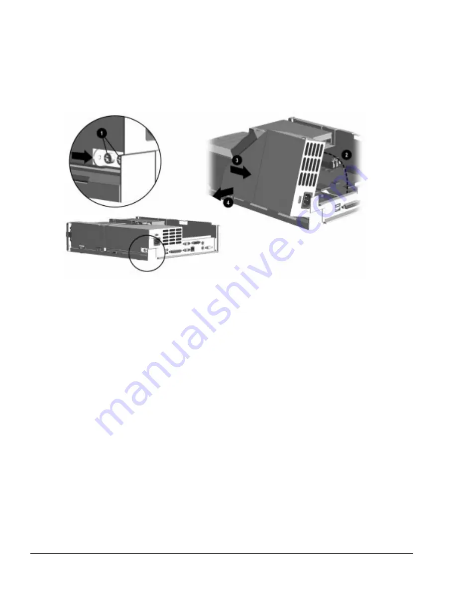
6. Loosen the two screws that secure the power supply hinge bracket
1
to the side of the chassis
and slide the bracket to the rear to disengage it from the power supply.
✎
It is not necessary to remove the hinge bracket for this operation.
7. Rotate the power supply up
2
, slide it to the rear
3
, and remove it from the chassis
4
.
Figure 5-12.
Removing the Easy Access Power Supply
To replace the power supply, complete the following steps:
1. Set the power supply down on the system board so that the built-in connector is resting on the
socket on the system board.
2. Push the hinge bracket into the hinge hole on the power supply. Hold the bracket in place with
one finger while tightening the rear retaining screw.
Ensure that there is no slack between the power supply, the chassis, and the hinge bracket.
3. Tighten the forward retaining screw to secure the hinge bracket.
4. Press the power supply down so that the built-in connector makes a good electrical connection
with the system board.
5. Continue with the balance of the installation sequence which is the reverse of the installation
process described above.
✎
When installing the expansion board cage, ensure that the tab on the cage latches into the slot
on the side of the power supply.
Summary of Contents for Deskpro 4000N - Desktop PC
Page 1: ...MAINTENANCE SERVICE GUIDE Compaq Deskpro 4000N and 4000S Network Personal Computers...
Page 2: ......
Page 4: ...CPS...
Page 22: ......
Page 46: ...3 2 Illustrated Parts Catalog 3 1 System Unit Figure 3 2 System Unit Spares...
Page 48: ...3 4 Illustrated Parts Catalog 3 2 Parts Kits Figure 3 3 Part Kits Components...
Page 50: ...3 6 Illustrated Parts Catalog 3 3 Miscellaneous Parts Figure 3 4 Miscellaneous Parts...
Page 52: ...3 8 Illustrated Parts Catalog 3 4 Mass Storage Devices Figure 3 5 Mass Storage Devices...
Page 54: ...3 10 Illustrated Parts Catalog 3 5 Cables Figure 3 6 Cables...
Page 58: ...3 14 Illustrated Parts Catalog 3 7 Keyboards Figure 3 8 Enhanced Keyboard...
Page 60: ...3 16 Illustrated Parts Catalog 3 8 Monitors Figure 3 9 Compaq Monitors...
Page 66: ......
Page 74: ......
Page 124: ...6 10 Connector Jumper and Switch Information...
Page 142: ......
Page 146: ......
Page 158: ......
Page 162: ......


