Compaq Deskpro 4000S and 4000N Personal Computers
5-21
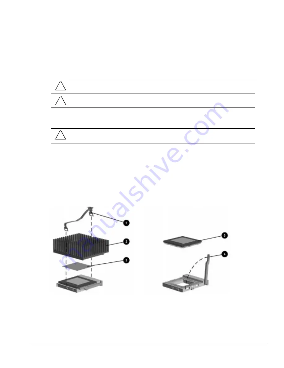
5.13.2 Microprocessor
To remove the microprocessor from the system board, complete the following steps:
1. Prepare the computer for disassembly (Section 5.4).
2. Remove the system unit cover (Section 5.7).
CAUTION:
When replacing the processor, you must release the heatsink retaining clip before you pull the
ZIF socket handle. The clip engages the processor socket to hold the heatsink in place.
!
WARNING:
To reduce the risk of personal injury from hot surfaces, allow the internal system components
to cool before touching.
3. Rotate the drive cage to an upright position.
CAUTION:
Check the position of all cables and wires before raising or lowering the drive cage to prevent
cable damage.
4. Remove the heatsink retaining clip
1
by pressing down on the clip’s extended tab until it
releases from the safety catch; then, pivot the tab to disengage it from the safety catch.
5. Lift the heatsink
2
off the processor.
6. Release the processor from the socket by pulling the handle on the ZIF socket out and
upward
4
.
7. Lift the processor
5
out of the socket.
Figure 5-15.
Removing the Microprocessor from the System Board
Summary of Contents for Deskpro 4000N - Desktop PC
Page 1: ...MAINTENANCE SERVICE GUIDE Compaq Deskpro 4000N and 4000S Network Personal Computers...
Page 2: ......
Page 4: ...CPS...
Page 22: ......
Page 46: ...3 2 Illustrated Parts Catalog 3 1 System Unit Figure 3 2 System Unit Spares...
Page 48: ...3 4 Illustrated Parts Catalog 3 2 Parts Kits Figure 3 3 Part Kits Components...
Page 50: ...3 6 Illustrated Parts Catalog 3 3 Miscellaneous Parts Figure 3 4 Miscellaneous Parts...
Page 52: ...3 8 Illustrated Parts Catalog 3 4 Mass Storage Devices Figure 3 5 Mass Storage Devices...
Page 54: ...3 10 Illustrated Parts Catalog 3 5 Cables Figure 3 6 Cables...
Page 58: ...3 14 Illustrated Parts Catalog 3 7 Keyboards Figure 3 8 Enhanced Keyboard...
Page 60: ...3 16 Illustrated Parts Catalog 3 8 Monitors Figure 3 9 Compaq Monitors...
Page 66: ......
Page 74: ......
Page 124: ...6 10 Connector Jumper and Switch Information...
Page 142: ......
Page 146: ......
Page 158: ......
Page 162: ......


