


5.
Checking the robot calibration position
·
If in order to reach the calibration position, the risk exists that the robot may collide with any equip-
ment, take the robot close to the calibration indexes (fixed and mobile index) moving the axes indi-
vidually; if not (robot working field completely free) perform the next operation immediately.
·
Select the EXEC (Execute) command on the PTU4
·
Activate the Help of the commands menu with the SHIFT and HELP keys; pressing ENTER selects
the instruction MOVE TO SCAL_SYS, confirm the command pressing ENTER twice.
·
Reduce the robot speed to 20% pressing the
key of the PTU4
·
Press the PTU4 Enabling Device button in the intermediate position, the robot motors turn on
(DRIVE ON led lit)
·
Press the START button and keep it pressed until reaching the calibration position. A message on
the PTU4 display will confirm the end of the movement. Physically check that the calibration in-
dexes (fixed and mobile index) coincide.
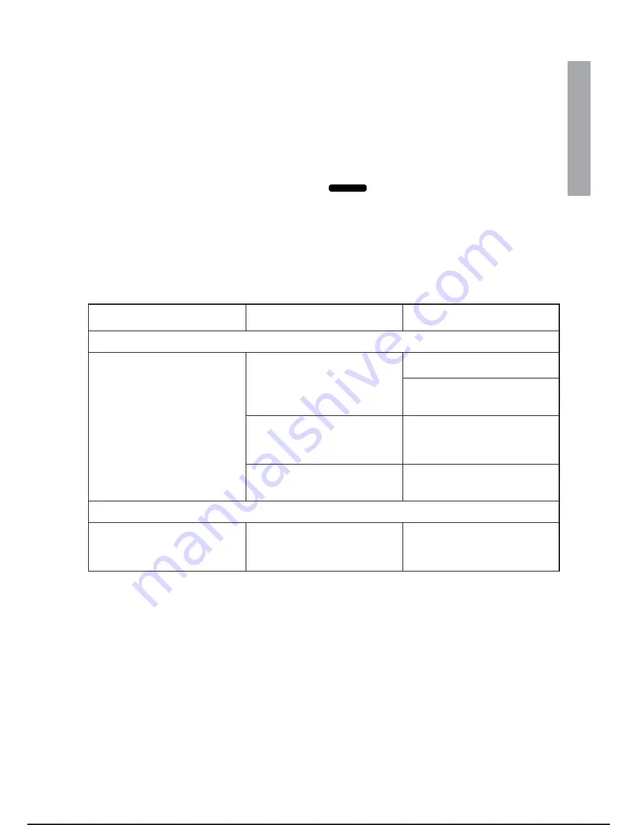
PROBLEMS DURING FUNCTIONAL TESTS
Fault
Check
Suggestions/Possible causes
1. Checking Enabling Device button and DRIVE ON
Pressing the Enabling Device but-
ton DRIVE ON is not performed
(motors off)
The PTU4 display shows RE-
MOTE DRIVE OFF
Wiring error on connector X30,
consult step 7 of the procedure
If relay K107 is present (optional
safety stop) check that it is working
properly
Presence of alarms on PTU4
Using the PCINT programme con-
sult the explanation (cause/rem-
edy) of the error message shown
(Operator Interface chapter)
If rack SAU2 is off
General check of fuses inside the
controller (see summary table in
maintenance chapter)
2. Checking safety devices
Presence of alarms on PTU4 refer-
ring to safety devices on which the
functional check is performed
Wiring on X30, external safety de-
vices installed
Errors in wiring of external safety
devices or fault on safety devices
installed (consult step 7 of the pro-
cedure)
C3G
Plus
INSTALLATION
08/0702
2-17
-
+
%
INSTALLATION
10.
Summary of Contents for C3G Plus
Page 6: ...This page has been intentionally blank UPDATING LIST C3G Plus D 08 0702 ...
Page 14: ...This page has been intentionally blank Operations and Maintenance Manual C3G Plus ...
Page 24: ...This page has been intentionally blank Operations and Maintenance Manual C3G Plus ...
Page 26: ...This page has been left intentionally blank INSTALLATION C3G Plus 2 ii 01 0498 SUMMARY ...
Page 48: ...This page has been intentionally blank Operations and Maintenance Manual C3G Plus ...
Page 122: ...This page has been intentionally blank Operations and Maintenance Manual C3G Plus ...
Page 127: ...C3G Plus INTEGRATION GUIDE 06 0400 4 5 SYSTEM I O ...
Page 160: ...This page has been intentionally blank Operations and Maintenance Manual C3G Plus ...
Page 182: ...This page has been intentionally blank Operations and Maintenance Manual C3G Plus ...
Page 188: ...This page has been intentionally blank Operations and Maintenance Manual C3G Plus ...
Page 190: ...This page has been left intentionally blank MAINTENANCE C3G Plus 7 ii 00 1097 GENERAL RULES ...
Page 225: ...X30 connector test device C3G Plus MAINTENANCE 01 0498 7 35 diagnostic ...
Page 264: ...This page has been intentionally blank 7 74 08 0702 MAINTENANCE C3G Plus LIST OF SPARE PARTS ...
Page 265: ...OPERATOR S NOTES C3G Plus NOTES ...
Page 266: ...C3G Plus NOTES ...