Contents
Page 36
•
Always make sure the rack is stable before extending a server or other
component from the rack.
•
You should extend only one server or component at a time - extending two or
more simultaneously may cause the rack to become unstable.
3.5
Server Precautions
•
Determine the placement of each component in the rack
before
you install
the rails.
•
Install the heaviest server components at the bottom of the rack first and
then work your way up.
•
Use a regulating uninterruptible power supply (UPS) to protect the server
from power surges and voltage spikes and to keep your system operating in
case of a power failure.
•
Allow any drives and power supply modules to cool before touching them.
•
When not servicing, always keep the front door of the rack and all
covers/panels on the servers closed to maintain proper cooling.
3.6
Rack Mounting Considerations
3.6.1
Ambient Operating Temperature
If installed in a closed or multi-unit rack assembly, the ambient operating
temperature of the rack environment may be greater than the room's ambient
temperature. Therefore, consideration should be given to installing the equipment in
an environment compatible with the ma
nufacturer’s maximum recommended
ambient temperature (TMRA).
3.6.1.1
Airflow
Equipment should be mounted into a rack so that the amount of airflow required for
safe operation is not compromised.
3.6.1.2
Mechanical Loading
Equipment should be mounted into a rack so that a hazardous condition does not
arise due to uneven mechanical loading.
Summary of Contents for UCS C890 M5
Page 15: ...Contents Page 15 Location of the C890 M5 BMC Card ...
Page 19: ...Contents Page 19 Five 5 C890 M5 PCIEBOARD on the Rear side of Midplane ...
Page 25: ...Contents Page 25 C890 M5 BPLANE Midplane Layout Rear Side ...
Page 26: ...Contents Page 26 Front View of the C890 M5 BPLANE Midplane ...
Page 27: ...Contents Page 27 Rear View of the C890 M5 BPLANE Midplane ...
Page 28: ...Contents Page 29 2 3 14 Location of the C890 M5 BPLANE Midplane The CPU Board ...
Page 44: ...Contents Page 46 ...
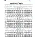
Page 48: ...Contents Page 50 Mixed DIMM DC PMem Population Table ...
Page 55: ...Contents Page 57 6 Pull the card out of the PCI E board Removing a PCI E Module 3 4 ...
Page 56: ...Contents Page 58 Removing a PCI E Card from a PCIE Module 5 6 ...
Page 59: ...Contents Page 61 Installing a PCI E Card in a CPU Module ...
Page 60: ...Contents Page 62 Installing a PCI E Card in a CPU Module cont ...
Page 62: ...Contents Page 64 Installing a PCI E Card in a Storage Module ...
Page 64: ...Contents Page 66 Installing the Battery 3 2 ...
Page 66: ...Contents Page 68 Mounting a Drive in a Carrier ...
Page 70: ...Contents Page 72 Removing the Storage Module Cover ...
Page 71: ...Contents Page 73 Installing Removing 2 5 HDDs with bracket ...
Page 86: ...90 Contents Page 90 ...
Page 90: ...95 Contents Page 95 ...
Page 163: ...Contents Page 168 Save changes and Reset ...
Page 165: ...Contents Page 170 ...
Page 167: ...Contents Page 172 ...
Page 168: ...Contents Page 173 ...
Page 169: ...Contents Page 174 Emulex FC ...
Page 171: ...Contents Page 176 ...
Page 178: ...BIOS PCIe Configuration Page 183 Save changes and Reset ...
Page 179: ...BIOS PCIe Configuration Page 184 Confirm by selecting yes ...
Page 182: ...BIOS PCIe Configuration Page 187 ...
Page 183: ...BIOS PCIe Configuration Page 188 ...
Page 184: ...BIOS PCIe Configuration Page 189 ...
Page 185: ...BIOS PCIe Configuration Page 190 ...
Page 186: ...BIOS PCIe Configuration Page 191 ...
Page 188: ...BIOS PCIe Configuration Page 193 Default is enabled ...
Page 190: ...BIOS PCIe Configuration Page 195 ...
Page 191: ...BIOS PCIe Configuration Page 196 ...


