Contents
Page 143
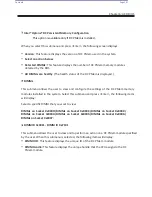
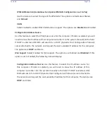
Select Enabled to enable SHA256 PCR Bank support to enhance system security and data
integrity. The options are
Enabled
and Disabled.
Pending Operation
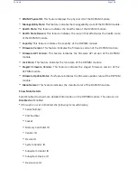
Use this feature to schedule a TPM-related operation to be performed by a security (TPM)
device at the next system boot to enhance system data integrity. The options are
None
and
TPM Clear.
Note
: Your system will reboot to carry out a pending TPM operation.
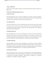
Platform Hierarchy (for TPM Version 2.0 and above)
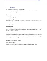
Select Enabled for TPM Platform Hierarchy support which will allow the manufacturer to utilize
the cryptographic algorithm to define a constant key or a fixed set of keys to be used for initial
system boot. These early boot codes are shipped with the platform and are included in the list
of "public keys". During system boot, the platform firmware uses the trusted public keys to
verify a digital signature in an attempt to manage and control the security of the platform
firmware used in a host system via a TPM device. The options are
Enabled
and Disabled.
Storage Hierarchy
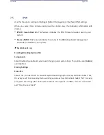
Select Enabled for TPM Storage Hierarchy support that is intended to be used for non-privacy-
sensitive operations by the platform owner such as an IT professional or the end user. Storage
Hierarchy has an owner policy and an authorization value, both of which can be set and are
held constant (-rarely changed) through reboots. This hierarchy can be cleared or changed
independently of the other hierarchies. The options are
Enabled
and Disabled.
Summary of Contents for UCS C890 M5
Page 15: ...Contents Page 15 Location of the C890 M5 BMC Card ...
Page 19: ...Contents Page 19 Five 5 C890 M5 PCIEBOARD on the Rear side of Midplane ...
Page 25: ...Contents Page 25 C890 M5 BPLANE Midplane Layout Rear Side ...
Page 26: ...Contents Page 26 Front View of the C890 M5 BPLANE Midplane ...
Page 27: ...Contents Page 27 Rear View of the C890 M5 BPLANE Midplane ...
Page 28: ...Contents Page 29 2 3 14 Location of the C890 M5 BPLANE Midplane The CPU Board ...
Page 44: ...Contents Page 46 ...
Page 48: ...Contents Page 50 Mixed DIMM DC PMem Population Table ...
Page 55: ...Contents Page 57 6 Pull the card out of the PCI E board Removing a PCI E Module 3 4 ...
Page 56: ...Contents Page 58 Removing a PCI E Card from a PCIE Module 5 6 ...
Page 59: ...Contents Page 61 Installing a PCI E Card in a CPU Module ...
Page 60: ...Contents Page 62 Installing a PCI E Card in a CPU Module cont ...
Page 62: ...Contents Page 64 Installing a PCI E Card in a Storage Module ...
Page 64: ...Contents Page 66 Installing the Battery 3 2 ...
Page 66: ...Contents Page 68 Mounting a Drive in a Carrier ...
Page 70: ...Contents Page 72 Removing the Storage Module Cover ...
Page 71: ...Contents Page 73 Installing Removing 2 5 HDDs with bracket ...
Page 86: ...90 Contents Page 90 ...
Page 90: ...95 Contents Page 95 ...
Page 163: ...Contents Page 168 Save changes and Reset ...
Page 165: ...Contents Page 170 ...
Page 167: ...Contents Page 172 ...
Page 168: ...Contents Page 173 ...
Page 169: ...Contents Page 174 Emulex FC ...
Page 171: ...Contents Page 176 ...
Page 178: ...BIOS PCIe Configuration Page 183 Save changes and Reset ...
Page 179: ...BIOS PCIe Configuration Page 184 Confirm by selecting yes ...
Page 182: ...BIOS PCIe Configuration Page 187 ...
Page 183: ...BIOS PCIe Configuration Page 188 ...
Page 184: ...BIOS PCIe Configuration Page 189 ...
Page 185: ...BIOS PCIe Configuration Page 190 ...
Page 186: ...BIOS PCIe Configuration Page 191 ...
Page 188: ...BIOS PCIe Configuration Page 193 Default is enabled ...
Page 190: ...BIOS PCIe Configuration Page 195 ...
Page 191: ...BIOS PCIe Configuration Page 196 ...

