Contents
Page 69
4.3.10.3
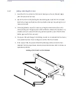
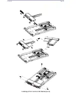
Installing a Hard Drive into a Drive Carrier
1.
Insert a drive into the carrier with the PCB side facing down and the
connector end toward the rear of the carrier.
2.
Align the drive in the carrier so that the mounting holes of both are aligned.
Note that there are holes in the carrier marked "SAS" or
“SATA”
to aid in
correct installation.
3.
Secure the drive to the carrier with four screws as illustrated above. Use the
four M3 flat-head screws included in the HDD bag of the accessory box.
Note that the screws used to secure the dummy drive to the carrier cannot
be used to secure the hard drive.
4.
Insert the hard drive and drive carrier into its bay, the release handle will
retract.
5.
Using the thumb, push against the upper part of the hard drive handle. Push
the hard drive into the hard drive bay as illustrated below, until the hard
drive clicks into the locked position.
4.3.10.4
Hard Drive Carrier Indicators
Each hard drive carrier has two LED indicators: an activity indicator and a status
indicator. In RAID configurations, the status indicator lights to indicate the status of
the drive. In non-RAID configurations, the status indicator remains off. See the table
below for details.
Hard Drive Carrier LED Indicators
LED
State/Condition
Indication
Blue
Blinking
Drive activity
Red
Solid on
Drive failure
Summary of Contents for UCS C890 M5
Page 15: ...Contents Page 15 Location of the C890 M5 BMC Card ...
Page 19: ...Contents Page 19 Five 5 C890 M5 PCIEBOARD on the Rear side of Midplane ...
Page 25: ...Contents Page 25 C890 M5 BPLANE Midplane Layout Rear Side ...
Page 26: ...Contents Page 26 Front View of the C890 M5 BPLANE Midplane ...
Page 27: ...Contents Page 27 Rear View of the C890 M5 BPLANE Midplane ...
Page 28: ...Contents Page 29 2 3 14 Location of the C890 M5 BPLANE Midplane The CPU Board ...
Page 44: ...Contents Page 46 ...
Page 48: ...Contents Page 50 Mixed DIMM DC PMem Population Table ...
Page 55: ...Contents Page 57 6 Pull the card out of the PCI E board Removing a PCI E Module 3 4 ...
Page 56: ...Contents Page 58 Removing a PCI E Card from a PCIE Module 5 6 ...
Page 59: ...Contents Page 61 Installing a PCI E Card in a CPU Module ...
Page 60: ...Contents Page 62 Installing a PCI E Card in a CPU Module cont ...
Page 62: ...Contents Page 64 Installing a PCI E Card in a Storage Module ...
Page 64: ...Contents Page 66 Installing the Battery 3 2 ...
Page 66: ...Contents Page 68 Mounting a Drive in a Carrier ...
Page 70: ...Contents Page 72 Removing the Storage Module Cover ...
Page 71: ...Contents Page 73 Installing Removing 2 5 HDDs with bracket ...
Page 86: ...90 Contents Page 90 ...
Page 90: ...95 Contents Page 95 ...
Page 163: ...Contents Page 168 Save changes and Reset ...
Page 165: ...Contents Page 170 ...
Page 167: ...Contents Page 172 ...
Page 168: ...Contents Page 173 ...
Page 169: ...Contents Page 174 Emulex FC ...
Page 171: ...Contents Page 176 ...
Page 178: ...BIOS PCIe Configuration Page 183 Save changes and Reset ...
Page 179: ...BIOS PCIe Configuration Page 184 Confirm by selecting yes ...
Page 182: ...BIOS PCIe Configuration Page 187 ...
Page 183: ...BIOS PCIe Configuration Page 188 ...
Page 184: ...BIOS PCIe Configuration Page 189 ...
Page 185: ...BIOS PCIe Configuration Page 190 ...
Page 186: ...BIOS PCIe Configuration Page 191 ...
Page 188: ...BIOS PCIe Configuration Page 193 Default is enabled ...
Page 190: ...BIOS PCIe Configuration Page 195 ...
Page 191: ...BIOS PCIe Configuration Page 196 ...

