Contents
Page 44
Memory Support and Installation
4.3.2
ESD Precautions
Electrostatic Discharge (ESD) can damage electronic components including memory
modules. To avoid damaging your DIMM modules, it is important to handle it very
carefully. The following measures are generally sufficient to protect your equipment
from ESD.
4.3.3
Precautions
•
Use a grounded wrist strap designed to prevent static discharge.
•
Handle the memory module by its edges only.
•
Put the memory modules into the antistatic bags when not in use.
4.3.4
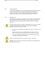
Introduction to Intel® Optane DC Persistent Memory
Intel® 82xx processor support the Intel
Optane™ DC Persistent Memory technology.
Intel Optane DC PMem offers data persistence with higher capacity at lower latencies
than the existing memory modules and provides hyper-speed storage capability for
high
performance computing platforms with flexible configuration options.
4.3.5
Memory Support
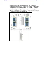
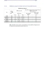
Each CPU board supports up to 3 TB DCPMM* or 3DS LRDIMM (Load Reduced)/
LRDIMM/3DS RDIMM (Registered)/RDIMM DDR4 memory of 2933 MHz in 12 DIMM
slots. It also supports up to 4.5 TB Intel Optane DC PMem and DDR4 combined
memory in12 DIMM slots. With eight CPU boards installed, your system will support
up to 24 TB of DDR4 memory or up to 36 TB Intel Optane DC PMem & DDR4
combined memory in 96 memory slots.
Summary of Contents for UCS C890 M5
Page 15: ...Contents Page 15 Location of the C890 M5 BMC Card ...
Page 19: ...Contents Page 19 Five 5 C890 M5 PCIEBOARD on the Rear side of Midplane ...
Page 25: ...Contents Page 25 C890 M5 BPLANE Midplane Layout Rear Side ...
Page 26: ...Contents Page 26 Front View of the C890 M5 BPLANE Midplane ...
Page 27: ...Contents Page 27 Rear View of the C890 M5 BPLANE Midplane ...
Page 28: ...Contents Page 29 2 3 14 Location of the C890 M5 BPLANE Midplane The CPU Board ...
Page 44: ...Contents Page 46 ...
Page 48: ...Contents Page 50 Mixed DIMM DC PMem Population Table ...
Page 55: ...Contents Page 57 6 Pull the card out of the PCI E board Removing a PCI E Module 3 4 ...
Page 56: ...Contents Page 58 Removing a PCI E Card from a PCIE Module 5 6 ...
Page 59: ...Contents Page 61 Installing a PCI E Card in a CPU Module ...
Page 60: ...Contents Page 62 Installing a PCI E Card in a CPU Module cont ...
Page 62: ...Contents Page 64 Installing a PCI E Card in a Storage Module ...
Page 64: ...Contents Page 66 Installing the Battery 3 2 ...
Page 66: ...Contents Page 68 Mounting a Drive in a Carrier ...
Page 70: ...Contents Page 72 Removing the Storage Module Cover ...
Page 71: ...Contents Page 73 Installing Removing 2 5 HDDs with bracket ...
Page 86: ...90 Contents Page 90 ...
Page 90: ...95 Contents Page 95 ...
Page 163: ...Contents Page 168 Save changes and Reset ...
Page 165: ...Contents Page 170 ...
Page 167: ...Contents Page 172 ...
Page 168: ...Contents Page 173 ...
Page 169: ...Contents Page 174 Emulex FC ...
Page 171: ...Contents Page 176 ...
Page 178: ...BIOS PCIe Configuration Page 183 Save changes and Reset ...
Page 179: ...BIOS PCIe Configuration Page 184 Confirm by selecting yes ...
Page 182: ...BIOS PCIe Configuration Page 187 ...
Page 183: ...BIOS PCIe Configuration Page 188 ...
Page 184: ...BIOS PCIe Configuration Page 189 ...
Page 185: ...BIOS PCIe Configuration Page 190 ...
Page 186: ...BIOS PCIe Configuration Page 191 ...
Page 188: ...BIOS PCIe Configuration Page 193 Default is enabled ...
Page 190: ...BIOS PCIe Configuration Page 195 ...
Page 191: ...BIOS PCIe Configuration Page 196 ...


