Preparing for Installation 2-15
Site Requirements
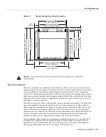
Figure 2-1
Chassis Footprint and Outer Dimensions
Caution
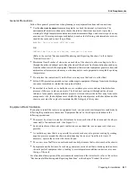
Never install the router in an enclosed rack that is not properly ventilated or
air-conditioned.
Site Environment
The router can operate as a standalone system placed on a table or as a rack-mounted system in a
data processing or lab environment. The fans operate at 55 percent of capacity when it is possible to
do so and maintain an acceptable operating temperature inside the chassis. If the temperature
exceeds 23°C, the fan speed increases linearly until it reaches 100 percent. Although the fans support
quieter operation under normal conditions (approximately 46 dBa), the noise level when the fans are
operating at 100-percent capacity is approximately 58 dBa. Therefore, the router is best suited for
unattended or computer room use.
The router requires a dry, clean, well-ventilated, and air-conditioned environment. The internal fan
array pulls ambient air through the chassis to cool the internal components. To allow sufficient
airflow, maintain a minimum of two inches of clearance on both the inlet and exhaust sides of the
chassis. If the airflow is blocked or restricted, or if the inlet air is too warm, an overtemperature
condition can occur. Under extreme conditions, the environmental monitor will shut down the power
to protect the system components. To help maintain normal operation and avoid unnecessary
maintenance, plan your site configuration and prepare your site before installation.
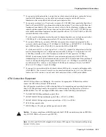
After installation, make sure that the site maintains an ambient temperature of 32 through 104°F
(0 through 40°C), and keep the area around the chassis as free from dust as is practical. For a
description of the environmental monitor and status levels, refer to the section “Environmental
Monitoring and Reporting Functions” in the chapter “Product Overview.”
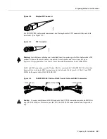
Noninterface processor end
Chassis foot C
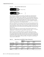
14.25 in. (36.20 cm)
Chassis width
17.50 in. (44.45 cm)
Fan tray
Chassis depth
17.0 in. (43.18 cm)
Chassis depth with power cord and cable
management bracket
19.0 in. (48.26 cm)
Interface processor width
14.55 in. (36.96 cm)
Power supply width
14.60 in. to ears (37.08 cm)
Interface processor depth
11.25 in. (28.58 cm)
Power supply depth
12.00 in. (30.48 cm)
1.25 in. (3.18 cm)
Interface processor end
H2818
2 in.
(5.08 cm)
Chassis foot C
13.32 in. (33.83 cm)
Summary of Contents for TelePresence Server 7010
Page 10: ...x Cisco 7010 Hardware Installation and Maintenence ...
Page 14: ...iv Cisco 7010 Hardware Installation and Maintenance Document Conventions ...
Page 148: ...3 36 Cisco 7010 Hardware Installation and Maintenance Using the Flash Memory Card ...
Page 158: ...4 10 Cisco 7010 Hardware Installation and Maintenance Troubleshooting the Processor Subsystem ...
Page 242: ...5 84 Cisco 7010 Hardware Installation and Maintenance Replacing Internal Components ...
Page 258: ...A 16 Cisco 7010 Hardware Installation and Maintenance MIP Interface Cable Pinouts ...
Page 270: ...B 12 Cisco 7010 Hardware Installation and Maintenance Interface Processor LEDs ...
Page 274: ...C 4 Cisco 7000 Hardware Installation and Maintenance ...
Page 287: ...Index 13 ...


