


Maintenance 5-75
Replacing Internal Components
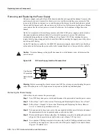
Note
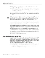
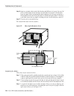
Before inserting the fan tray, compare the hardware inside the chassis to Figure 5-26. The
runner on the bottom of the fan tray has to slide along in the track on the floor. At the same time, the
runner on the top of the tray has to slide through the notch at the top of the chassis opening, then over
the top of the card cage while staying to the left of the L-bracket on the chassis ceiling.
Figure 5-25
Replacing the Fan Tray
Removing/replacing
fan tray
H1996
Summary of Contents for TelePresence Server 7010
Page 10: ...x Cisco 7010 Hardware Installation and Maintenence ...
Page 14: ...iv Cisco 7010 Hardware Installation and Maintenance Document Conventions ...
Page 148: ...3 36 Cisco 7010 Hardware Installation and Maintenance Using the Flash Memory Card ...
Page 158: ...4 10 Cisco 7010 Hardware Installation and Maintenance Troubleshooting the Processor Subsystem ...
Page 242: ...5 84 Cisco 7010 Hardware Installation and Maintenance Replacing Internal Components ...
Page 258: ...A 16 Cisco 7010 Hardware Installation and Maintenance MIP Interface Cable Pinouts ...
Page 270: ...B 12 Cisco 7010 Hardware Installation and Maintenance Interface Processor LEDs ...
Page 274: ...C 4 Cisco 7000 Hardware Installation and Maintenance ...
Page 287: ...Index 13 ...


