Maintenance 5-21
Installing and Configuring Processor Modules
Bit 8 controls the console Break key. Setting bit 8 (the factory default) causes the processor to ignore
the console Break key. Clearing bit 8 causes the processor to interpret the Break key as a command
to force the system into the bootstrap monitor, thereby halting normal operation. A break can be sent
in the first 60 seconds while the system reboots, regardless of the configuration settings.
Bit 9 controls the secondary bootstrap program function. Setting bit 9 causes the system to use the
secondary bootstrap; clearing bit 9 causes the system to ignore the secondary bootstrap. The
secondary bootstrap program is used for system debugging and diagnostics.
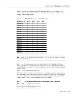
Bit 10 controls the host portion of the IP broadcast address. Setting bit 10 causes the processor to
use all zeros; clearing bit 10 (the factory default) causes the processor to use all ones. Bit 10 interacts
with bit 14, which controls the network and subnet portions of the broadcast address. Table 5-7
shows the combined effect of bits 10 and 14.
Table 5-7
Configuration Register Settings for Broadcast Address Destination
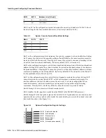
Bits 11 and 12 in the configuration register determine the baud rate of the console terminal.
Table 5-8 shows the bit settings for the four available baud rates. (The factory-set default baud rate
is 9,600.)
Table 5-8
System Console Terminal Baud Rate Settings
Bit 13 determines the server response to a boot-load failure. Setting bit 13 causes the server to load
operating software from ROM after five unsuccessful attempts to load a boot file from the network.
Clearing bit 13 causes the server to continue attempting to load a boot file from the network
indefinitely. By factory default, bit 13 is cleared to 0.
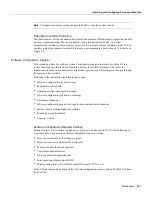
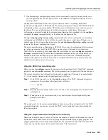
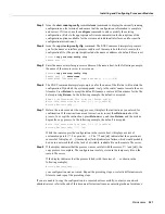
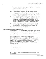
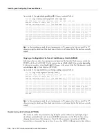
Enabling Booting from Flash Memory
To enable booting from Flash, set configuration register bits 3, 2, 1, and 0 to a value between 2 and
15 in conjunction with the boot system flash [filename] configuration command.
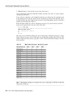
To enter configuration mode while in the system software image and specify a Flash filename from
which to boot, enter the configure terminal command at the enable prompt, as follows:
Router# configure terminal
Enter configuration commands, one per line. End with CTRL/Z.
boot system flash [filename]
Bit 14
Bit 10
Address (<net> <host>)
Off
Off
<ones> <ones>
Off
On
<zeros> <zeros>
On
On
<net> <zeros>
On Off
<net>
<ones>
Baud
Bit 12
Bit 11
9,600
0
0
4,800
0
1
1,200
1
0
2,400
1
1
Summary of Contents for TelePresence Server 7010
Page 10: ...x Cisco 7010 Hardware Installation and Maintenence ...
Page 14: ...iv Cisco 7010 Hardware Installation and Maintenance Document Conventions ...
Page 148: ...3 36 Cisco 7010 Hardware Installation and Maintenance Using the Flash Memory Card ...
Page 158: ...4 10 Cisco 7010 Hardware Installation and Maintenance Troubleshooting the Processor Subsystem ...
Page 242: ...5 84 Cisco 7010 Hardware Installation and Maintenance Replacing Internal Components ...
Page 258: ...A 16 Cisco 7010 Hardware Installation and Maintenance MIP Interface Cable Pinouts ...
Page 270: ...B 12 Cisco 7010 Hardware Installation and Maintenance Interface Processor LEDs ...
Page 274: ...C 4 Cisco 7000 Hardware Installation and Maintenance ...
Page 287: ...Index 13 ...


