Installing the Router 3-29
Using the Flash Memory Card
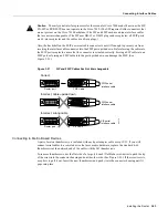
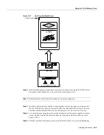
Figure 3-27
Installing the Metal Sleeve
Step 2
Hold the Flash memory card with the connector end of the card toward the PCMCIA slot.
The product label should face to the right, as shown in Figure 3-28a.
Note
The Flash memory card is keyed and cannot be seated the wrong way.
Step 3
Insert the card into the slot until the card completely seats in the connector at the back of
the slot. Note that the card does not insert all the way inside the RP; a portion of the card
and sleeve remain outside of the slot. Do not attempt to force the card past this point.
Step 4
To remove the card, grasp the card near the slot and squeeze the sleeve together to release
it from the slot. Then pull the card free from the connector at the back of the slot. (See
Figure 3-28c.)
Step 5
Place the removed Flash memory card on an antistatic surface or in a static shielding bag.
Series 2+
8 MByte Memory Card
PERFORMANCE PLUS
CAUTION!
H4225
Connector end
Summary of Contents for TelePresence Server 7010
Page 10: ...x Cisco 7010 Hardware Installation and Maintenence ...
Page 14: ...iv Cisco 7010 Hardware Installation and Maintenance Document Conventions ...
Page 148: ...3 36 Cisco 7010 Hardware Installation and Maintenance Using the Flash Memory Card ...
Page 158: ...4 10 Cisco 7010 Hardware Installation and Maintenance Troubleshooting the Processor Subsystem ...
Page 242: ...5 84 Cisco 7010 Hardware Installation and Maintenance Replacing Internal Components ...
Page 258: ...A 16 Cisco 7010 Hardware Installation and Maintenance MIP Interface Cable Pinouts ...
Page 270: ...B 12 Cisco 7010 Hardware Installation and Maintenance Interface Processor LEDs ...
Page 274: ...C 4 Cisco 7000 Hardware Installation and Maintenance ...
Page 287: ...Index 13 ...

