Maintenance 5-69
Installing and Configuring Processor Modules
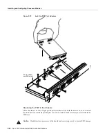
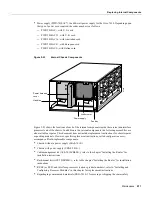
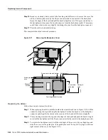
Figure 5-22
Installing an E1 Port Adapter
Step 6
Place your fingers over the BTB connector and firmly (but gently) press down until the
BTB connector mates with the MIP connector. If the connector resists, do not force it. Shift
the port adapter around until the connectors mate properly.
Step 7
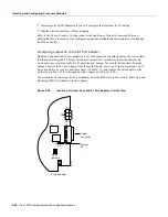
Insert the four long Phillips screws through the four port adapter holes and finger-tighten
them. These screws extend through the standoffs and the MIP board and thread into the
metal carrier.
Step 8
Install a lockwasher on each of the two jackscrews.
H2741
Summary of Contents for TelePresence Server 7010
Page 10: ...x Cisco 7010 Hardware Installation and Maintenence ...
Page 14: ...iv Cisco 7010 Hardware Installation and Maintenance Document Conventions ...
Page 148: ...3 36 Cisco 7010 Hardware Installation and Maintenance Using the Flash Memory Card ...
Page 158: ...4 10 Cisco 7010 Hardware Installation and Maintenance Troubleshooting the Processor Subsystem ...
Page 242: ...5 84 Cisco 7010 Hardware Installation and Maintenance Replacing Internal Components ...
Page 258: ...A 16 Cisco 7010 Hardware Installation and Maintenance MIP Interface Cable Pinouts ...
Page 270: ...B 12 Cisco 7010 Hardware Installation and Maintenance Interface Processor LEDs ...
Page 274: ...C 4 Cisco 7000 Hardware Installation and Maintenance ...
Page 287: ...Index 13 ...


