1-36 Cisco 7010 Hardware Installation and Maintenance
Functional Overview
Interface ports maintain the same address regardless of whether other interface processors are
installed or removed. However, when you move an interface processor to a different slot, the first
number in the address changes to reflect the new slot number. For example, on a six-port EIP in slot
1, the address of the first port (on the left) is 1/0 and that of the right-most port is 1/5. If you remove
the EIP from slot 1 and install it in slot 2, the addresses of those same ports become 2/0 and 2/5.
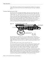
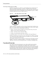
Figure 1-24 shows some of the port numbers of a sample system.
Figure 1-24
Interface Port Address Examples
Interface slots are numbered 0 to 2 from the bottom slot up. The port numbers always begin at 0 and
are numbered from left to right. The number of additional ports (/1, /2, and so on) depends on the
number of ports available on an interface. FDDI interfaces are always n/0, because each FIP supports
one interface. (The multiple connectors on the FIP can be misleading, but they provide multiple
attachment options for a single FDDI interface.) Ethernet interfaces can be numbered from /0
through /5 because EIPs support up to six Ethernet ports. Serial interfaces on an eight-port FSIP are
numbered /0 through /7, and so on.
You can identify interface ports by physically checking the slot/port location on the back of the
router or by using software commands to display information about a specific interface or all
interfaces in the router. To display information about every interface, use the show interfaces
command (interfaces is plural) without variables. To display information about a specific interface,
use the show interface command (interface is singular) with the interface type and port address in
the format show interface [type slot/port]. If you abbreviate the command (sho int) and do not
include variables, the system interprets the command as show interfaces and displays the status of
all interfaces.
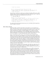
Following is an example of how the show interfaces command, which you use without variables,
displays status information (including the physical slot and port address) for each interface in the
router.
In the following example, most of the status information for each interface is omitted.
7010# show int
Serial0/0 is up, line protocol is up
Hardware is cxBus Serial
Internet address is 131.108.123.4, subnet mask is 255.255.255.0
(display text omitted)
Ethernet1/2 is up, line protocol is up
Hardware is cxBus Ethernet, address is 0000.0c02.d0f1 (bia 0000.0c02.d0f1)
H2041
Interface processor slot 0
Interface processor slot 1
Interface processor slot 2
SP slot
RP slot
2/0
1/0
0/2
0/5
Summary of Contents for TelePresence Server 7010
Page 10: ...x Cisco 7010 Hardware Installation and Maintenence ...
Page 14: ...iv Cisco 7010 Hardware Installation and Maintenance Document Conventions ...
Page 148: ...3 36 Cisco 7010 Hardware Installation and Maintenance Using the Flash Memory Card ...
Page 158: ...4 10 Cisco 7010 Hardware Installation and Maintenance Troubleshooting the Processor Subsystem ...
Page 242: ...5 84 Cisco 7010 Hardware Installation and Maintenance Replacing Internal Components ...
Page 258: ...A 16 Cisco 7010 Hardware Installation and Maintenance MIP Interface Cable Pinouts ...
Page 270: ...B 12 Cisco 7010 Hardware Installation and Maintenance Interface Processor LEDs ...
Page 274: ...C 4 Cisco 7000 Hardware Installation and Maintenance ...
Page 287: ...Index 13 ...

