2-4 Cisco 7010 Hardware Installation and Maintenance
Site Requirements
•
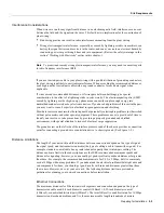
Handle interface processors by the handles and carrier edges only; avoid touching the board or
any connector pins.
•
When removing an RP, SP (or SP), interface processor, or the arbiter, place the removed
component board-side-up on an antistatic surface or in a static shielding bag. If the component
will be returned to the factory, immediately place it in a static shielding bag.
•
Handle bare boards (such as the arbiter board) by the edges only.
•
Avoid contact between the board or interface processor and clothing. The wrist strap only
protects the card from ESD voltages on the body; ESD voltages on clothing can still cause
damage.
Caution
For safety, periodically check the resistance value of the antistatic strap. The measurement
should be between 1 and 10 megohm.
Site Requirements
The environmental monitoring in the router protects the system and components from potential
damage from overvoltage and overtemperature conditions. To assure normal operation and avoid
unnecessary maintenance, plan your site configuration and prepare your site before installation.
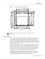
After installation, make sure the site maintains an ambient temperature of 32°F through 104°F (0°C
through 40°C), and keep the area around the chassis as free from dust as is practical.
The following sections address the site environment requirements for the router.
AC and DC Power
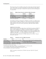
The 550W, wide-input, AC-input power supply uses a power factor corrector (PFC) that allows it to
operate on input voltages between 100 an 240 VAC and 50 through 60 Hz. Table 1-2 lists system
power specifications, including input voltage and operating frequency ranges. Install a power
conditioner between the AC line input and the router to help avoid network outages caused by power
spikes and brownouts, and to help protect against equipment damage from lightning strikes. The
600W, DC-input power supply allows the Cisco 7010 to operate between –40 and –52 VDC
(–48 VDC nominal). In the European Community, the power supply operates between –56 VDC and
–72 VDC (–60 VDC nominal).
Plant Wiring
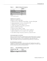
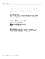
Following are guidelines for setting up the plant wiring and cabling at your site. When planning the
location of the new system, consider the distance limitations for signaling, electromagnetic
interference, and connector compatibility, as described in the following sections.
Summary of Contents for TelePresence Server 7010
Page 10: ...x Cisco 7010 Hardware Installation and Maintenence ...
Page 14: ...iv Cisco 7010 Hardware Installation and Maintenance Document Conventions ...
Page 148: ...3 36 Cisco 7010 Hardware Installation and Maintenance Using the Flash Memory Card ...
Page 158: ...4 10 Cisco 7010 Hardware Installation and Maintenance Troubleshooting the Processor Subsystem ...
Page 242: ...5 84 Cisco 7010 Hardware Installation and Maintenance Replacing Internal Components ...
Page 258: ...A 16 Cisco 7010 Hardware Installation and Maintenance MIP Interface Cable Pinouts ...
Page 270: ...B 12 Cisco 7010 Hardware Installation and Maintenance Interface Processor LEDs ...
Page 274: ...C 4 Cisco 7000 Hardware Installation and Maintenance ...
Page 287: ...Index 13 ...


