5-68 Cisco 7010 Hardware Installation and Maintenance
Installing and Configuring Processor Modules
Step 4
Remove the jackscrews and washers and put them aside.
Step 5
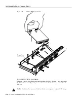
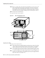
Use a number 1 Phillips screwdriver to loosen and remove the four standoff screws. (See
Figure 5-21.) The port adapter is now held in place only by the plastic BTB connector.
Step 6
While avoiding contact with any traces or components on the board, insert your thumb and
forefinger under the extension behind the BTB connector and gently lift the adapter upward
to dislodge it from the MIP connector. If the port adapter resists, rock it very slightly from
side to side until it pulls free of the MIP connector.
Caution
To prevent damage to the MIP, do not pry the port adapter out with a screwdriver or any
other tool. In particular, do not use the board stiffener for leverage.
Step 7
When the port adapter is completely disconnected from the MIP connector, tilt the back of
the port adapter up at about a 70-degree angle from vertical and slowly pull it up and out
(using the orientation shown in Figure 5-21) and away from the faceplate. The MIP cable
connector will pull out of the cutout in the faceplate.
Step 8
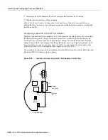
To reconfigure jumpers on the E1 port adapter, refer to the section “Configuring Jumper J6
on the E1 Port Adapter.” After you have set the jumpers, proceed to the next section
“Replacing a Port Adapter.”
Caution
To prevent overheating chassis components, do not reinstall the MIP in the chassis unless
all port adapters are in place. The empty port will allow cooling air to escape freely through the
cutouts in the faceplate, which could misdirect the airflow inside the chassis and allow components
on other boards to overheat.
Replacing a Port Adapter
If necessary, refer to the previous section to remove an E1 port adapter from the MIP. Refer to
Figure 5-22 while you perform the following steps:
Step 1
Ensure that the MIP is resting on an antistatic mat or on antistatic foam and position it with
the same orientation as that shown in Figure 5-22. You should still be wearing an
ESD-preventive ground strap.
Step 2
Handle the port adapter by the board edges only.
Step 3
Position the port adapter so that it is in the orientation shown in Figure 5-22: at about a
70-degree angle from vertical, component-side down, standoffs on the underside, and the
external interface cable connector facing the inside of the carrier faceplate.
Step 4
As shown in Figure 5-22, partially insert the cable connector through the back of the cutout
in the carrier faceplate. Do not force the cable connector through the cutout until the
standoffs and BTB connector is aligned.
Step 5
With the cable connector partially inserted into the faceplate cutout, slowly lower the back
(opposite) side of the port adapter. Continue to ease the cable connector through the cutout
until the BTB connector and the MIP and port adapter meet and the standoffs on the MIP
are aligned with the standoff holes in the port adapter. Shift the port adapter until the cable
connector is fully inserted through the cutouts and the standoffs are aligned with the
standoff holes. (See Figure 5-22.)
Summary of Contents for TelePresence Server 7010
Page 10: ...x Cisco 7010 Hardware Installation and Maintenence ...
Page 14: ...iv Cisco 7010 Hardware Installation and Maintenance Document Conventions ...
Page 148: ...3 36 Cisco 7010 Hardware Installation and Maintenance Using the Flash Memory Card ...
Page 158: ...4 10 Cisco 7010 Hardware Installation and Maintenance Troubleshooting the Processor Subsystem ...
Page 242: ...5 84 Cisco 7010 Hardware Installation and Maintenance Replacing Internal Components ...
Page 258: ...A 16 Cisco 7010 Hardware Installation and Maintenance MIP Interface Cable Pinouts ...
Page 270: ...B 12 Cisco 7010 Hardware Installation and Maintenance Interface Processor LEDs ...
Page 274: ...C 4 Cisco 7000 Hardware Installation and Maintenance ...
Page 287: ...Index 13 ...


