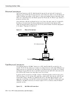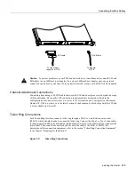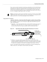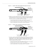
Installing the Router 3-7
Installing the Cable Management Brackets
If you do not mount the router in a rack, follow these steps to install the router on a bench or tabletop:
Step 1
Make sure that the area where you install the router is free of debris and dust. Also make
sure your path between the router and its planned location is unobstructed.
Step 2
On the chassis, ensure that all captive screws (on the processor modules and on the access
cover) are tightened and the components are secure.
Warning
To prevent damage, never attempt to lift or tilt the chassis with the handles on the interface
processors. These handles are not designed to support the weight of the chassis.
Step 3
Lift the chassis by placing your hands around the chassis sides and lifting the chassis from
underneath. Avoid sudden twists or moves to prevent injury.
Step 4
Place the router in a location where the air inlet vents on the side of the chassis are not
obstructed, nor are they drawing in exhaust air from other equipment.
Step 5
Ensure that the new location allows adequate clearance around the chassis for maintenance.
Step 6
After the router is in place, proceed to the next section to connect the interface cables.
Installing the Cable Management Brackets
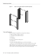
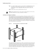
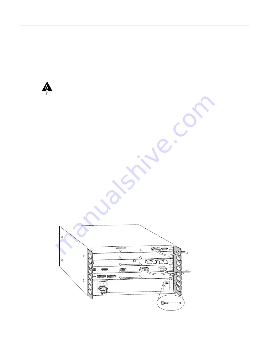
The cable management brackets (shown in Figure 3-5) attach to the inner sides of the chassis at the
interface processor end. Use the brackets to keep network interface cables untangled and orderly, and
to prevent cables from hindering access to interface processors in the lower interface processor slots.
Install the brackets before connecting network interface cables to the interface processor ports;
otherwise, you will probably need to disconnect the cables to install the screws that secure the
brackets. Route interface cables through the cable management brackets as you connect them to the
interface processor ports. If necessary, wrap cable ties through the holes provided to secure
small-gauge cables.
Figure 3-5
Cable Management Brackets
H2045
Summary of Contents for TelePresence Server 7010
Page 10: ...x Cisco 7010 Hardware Installation and Maintenence ...
Page 14: ...iv Cisco 7010 Hardware Installation and Maintenance Document Conventions ...
Page 148: ...3 36 Cisco 7010 Hardware Installation and Maintenance Using the Flash Memory Card ...
Page 158: ...4 10 Cisco 7010 Hardware Installation and Maintenance Troubleshooting the Processor Subsystem ...
Page 242: ...5 84 Cisco 7010 Hardware Installation and Maintenance Replacing Internal Components ...
Page 258: ...A 16 Cisco 7010 Hardware Installation and Maintenance MIP Interface Cable Pinouts ...
Page 270: ...B 12 Cisco 7010 Hardware Installation and Maintenance Interface Processor LEDs ...
Page 274: ...C 4 Cisco 7000 Hardware Installation and Maintenance ...
Page 287: ...Index 13 ...

