1-40 Cisco 7010 Hardware Installation and Maintenance
Functional Overview
Router#
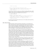
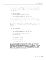
The microcode version and description lists the bundled microcode version for each processor type,
which is not necessarily the version that is currently loaded and running in the system. A microcode
image that is loaded from ROM or a Flash memory file is not shown in this display. To display the
currently loaded and running microcode version for each processor type, issue the show controller
cxbus command.
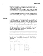
The target hardware version lists the minimum hardware revision required to ensure compatibility
with the new software and microcode images. When you load and boot from a new bundled image,
the system checks the hardware version of each processor module that it finds installed and compares
the actual version to its target list. If the target hardware version is different from the actual hardware
version, a warning message appears when you boot the router, indicating that there is a disparity
between the target hardware and the actual hardware. You will still be able to load the new image;
however, contact a service representative for information about upgrades and future compatibility
requirements.
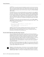
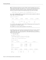
To display the current microcode version for each interface processor, enter the show controller
cxbus command. The following example shows that the SP is running Microcode Version 1.4, and
the FSIP is running Microcode Version 1.0:
7010# show cont cxbus
Switch Processor 5, hardware version 1.1, microcode version 1.4
(display text omitted)
FSIP 0, hardware version 4, microcode version 1.0
(display text omitted)
Although most microcode upgrades are distributed on floppy disk, some exceptions may require
ROM replacement. If so, refer to the chapter “Maintenance” for replacement procedures.
Instructions are also provided with the upgrade kit. For complete command descriptions and
instructions, refer to the related software documentation.
Environmental Monitoring and Reporting Functions
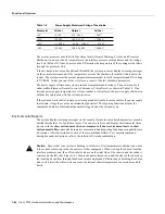
The environmental monitoring and reporting functions enable you to maintain normal system
operation by identifying and resolving adverse conditions prior to loss of operation. Environmental
monitoring functions constantly monitor the internal chassis air temperature and DC line voltages.
The power supply monitors its own voltage and temperature and shuts itself down if it detects a
critical condition within the power supply. If conditions reach shutdown thresholds, the system shuts
down to avoid equipment damage from excessive heat or current. The reporting functions
periodically log the values of measured parameters so that you can retrieve them for analysis later,
and the reporting functions display warnings on the console if any of the monitored parameters
exceed defined thresholds.
In addition to monitoring internal temperature and voltage levels, the system also monitors the fan
array. If any one or more of the fans fail, the system displays a warning message on the console. If
the fan is still not operating properly after two minutes, the system shuts down to protect the internal
components against damage from excessive heat.
Timesaver
With Maintenance Release 9.17(10) and later, the system can identify which type of
power supplies are in your chassis: DC-input or AC-input. As a general precaution, use the show
environment all command and note the type of power supply indicated in each of your chassis
(indicated as either “600W DC” or “550W AC”). Record and save this information in a secure place.
Summary of Contents for TelePresence Server 7010
Page 10: ...x Cisco 7010 Hardware Installation and Maintenence ...
Page 14: ...iv Cisco 7010 Hardware Installation and Maintenance Document Conventions ...
Page 148: ...3 36 Cisco 7010 Hardware Installation and Maintenance Using the Flash Memory Card ...
Page 158: ...4 10 Cisco 7010 Hardware Installation and Maintenance Troubleshooting the Processor Subsystem ...
Page 242: ...5 84 Cisco 7010 Hardware Installation and Maintenance Replacing Internal Components ...
Page 258: ...A 16 Cisco 7010 Hardware Installation and Maintenance MIP Interface Cable Pinouts ...
Page 270: ...B 12 Cisco 7010 Hardware Installation and Maintenance Interface Processor LEDs ...
Page 274: ...C 4 Cisco 7000 Hardware Installation and Maintenance ...
Page 287: ...Index 13 ...

