


9.
If the chassis is being replaced, use the 10-mm socket wrench to remove the ground cable from the
grounding point on top of the chassis rear (MSC) side panel.
DETAILED STEPS
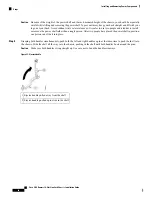
Step 1
Attach the ESD-preventive wrist strap to your wrist and connect its leash to one of the ESD connection sockets on the
rear (MSC) side of the chassis or a bare metal surface on the chassis.
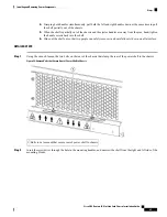
Step 2
Using a 10 mm socket wrench, loosen the two M6 hex nuts that attach the grounding L-bracket to the power shelf. Do
not fully remove.
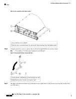
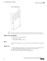
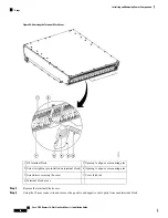
Figure 39: Grounding Brackets
Two M6 hex nuts attaching grounding L-bracket to shelf
grounding bracket (Step 4)
5
Chassis ground cable
1
Grounding L-bracket (Step 5)
6
Two M6 hex bolts attaching ground lug to chassis
2
Cisco CRS Routers 16-Slot Line Card Chassis Installation Guide
71
Installing and Removing Power Components
Steps