
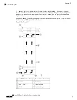


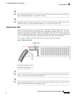


The power supply terminal posts are centered 0.63 inches (5/8 inch) (1.60 cm) apart and are M6-threaded.
We recommend that you use an appropriately sized 180-degree angle (straight) industry standard 2-hole,
standard barrel compression lug, as shown in this figure.
Figure 16: DC Power Cable Lug
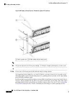
The power shelf grounding is accomplished by installing an external ground bracket between the power shelves
and attached to the chassis. The bolts that connect the external grounding brackets to the chassis and the power
shelf have a torque value of 30 in.-lb (3.39 N-m).
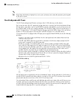
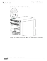
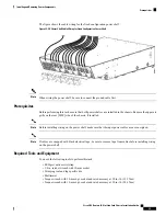
Input-Power-Present LEDs
In both power configurations, the DC input-power-present LEDs provide a visual indication to service personnel
that there is voltage present across the input terminal connection. The LED provides a warning to the service
person that there is power present.
Power should be disconnected before servicing the input power connection.
Note
This figure shows the input-power-present LEDs on the rear of the fixed configuration DC power shelf.
Cisco CRS Routers 16-Slot Line Card Chassis Installation Guide
25
Installing and Removing Power Components
Input-Power-Present LEDs