


• Although we recommend at least 6 AWG multistrand copper ground cable, the actual cable diameter
and length depends on the router location and site environment. This cable is not available from Cisco
Systems; it is available from any commercial cable vendor. The cable should be sized according to local
and national installation requirements.
The DC return of this system should remain isolated from the system frame and chassis (DC-I: Isolated DC
Return).
Note
Required Tools and Equipment
• Ground lug
• Ground cable
• Crimping tool and lug specific die
• 10-mm 6 pt. combination wrench
• Torque wrench with 10-mm 6 pt. socket and rated accuracy at 30 in.-lb (3.39 N-m)
Steps
To attach the ground cable to the chassis, follow these steps:
SUMMARY STEPS
1.
Use the crimping tool mandated by the lug manufacturer to crimp the lug to the ground cable.
2.
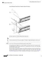
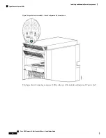
Using the 10-mm wrench, attach the ground cable to the grounding point on top of the chassis rear (MSC)
side panel, as shown
Figure 9: NEBS Bonding and Grounding Points—Modular Configuration DC Power
. Then use the torque wrench to tighten to a torque of 30 in.-lb (3.39 N-m).
DETAILED STEPS
Step 1
Use the crimping tool mandated by the lug manufacturer to crimp the lug to the ground cable.
Step 2
Using the 10-mm wrench, attach the ground cable to the grounding point on top of the chassis rear (MSC) side panel, as
shown
Figure 9: NEBS Bonding and Grounding Points—Modular Configuration DC Power Shown
. Then use the torque
wrench to tighten to a torque of 30 in.-lb (3.39 N-m).
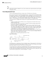
DC Power Systems
Each DC powered chassis contains two DC power shelves for 2N redundancy. The shelves contain the input
power connectors.
• In the fixed configuration power system, each power shelf contains three DC PEMs. The power shelves
and DC PEMs are field replaceable. Each DC PEM has its own circuit breaker.
• In the modular configuration power system, each shelf can accept up to eight DC PMs. The power shelves
and DC PMs are field replaceable.
Cisco CRS Routers 16-Slot Line Card Chassis Installation Guide
21
Installing and Removing Power Components
Required Tools and Equipment