


DETAILED STEPS
Step 1
Attach the ESD-preventive wrist strap to your wrist and connect its leash to one of the ESD connection sockets on the
front (PLIM) side of the chassis or a bare metal surface on the chassis.
Step 2
Remove the upper grille on the front (PLIM) side of the chassis. For detailed instructions, see
Installing and Removing
Exterior Cosmetic Components
.
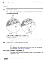
Step 3
Use the screwdriver to loosen the two captive screws securing the alarm module to the power shelf.
Step 4
Loosen by hand the panel fasteners on the alarm module.
Step 5
Carefully slide the alarm module out of the power shelf.
What to do next
After performing this task, install a replacement alarm module (if necessary) and re-install the upper grille on
the front (PLIM) side of the chassis.
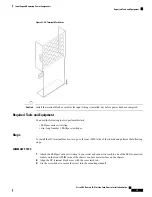
Installing a Modular Configuration Power Module
This section describes how to install the AC or DC PMs in the LCC.
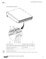
Figure 47: Modular Configuration PM
Cisco CRS Routers 16-Slot Line Card Chassis Installation Guide
85
Installing and Removing Power Components
Installing a Modular Configuration Power Module


