


SUMMARY STEPS
1.
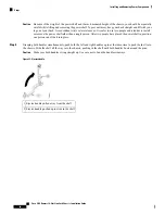
Attach the ESD-preventive wrist strap to your wrist and connect its leash to one of the ESD connection
sockets on the front (PLIM) side of the chassis or a bare metal surface on the chassis.
2.
Make sure that the safety ground wiring is connected.
3.
Make sure that the facility power breakers for the upper (PS0) and lower (PS1) power shelves are in
the OFF position.
4.
Make sure that all the I/0 switches are in an OFF position. That is, make sure all I/O levers are pulled
out. There are total of six power levers for the six AC power rectifiers and two power levers for the two
AC power shelves.
5.
Make sure all boards (RPs, PLIMs, SFCs, and FPs) are pulled-out and disconnected from the backplane.
6.
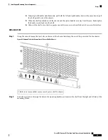
Remove the cover plate from the rear of each fixed configuration AC power shelf.
7.
Plug in AC power cords for the upper (PS0) and lower (PS1) power shelf.
8.
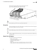
For AC Delta and AC Wye, verify the following resistance values, as shown in
and
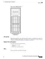
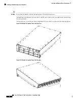
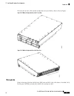
Figure 21: AC Delta Power Shelf Rear
), for the upper (PS0) and
lower (PS1) power shelf:
9.
Make sure that each input power cable one is connected, and energize the facility breaker to each input.
10.
Measure the voltage between the following, for the upper (PS0) and lower (PS1) power shelf:
11.
Turn the facility breaker for the upper (PS0) and lower (PS1) power shelf to the OFF position.
12.
Turn the facility breaker for the upper (PS0) and lower power shelf (PS1) to the ON position.
13.
Turn the power shelf I/O switches on both power shelves (PS0 and PS1) to the ON position. Verify that
the “CBREAKER TRIP” LED on the front panel of each power rectifier is yellow and that no other
LEDs are active.
14.
Turn the first power rectifier (A0) I/O switch on the upper power shelf (PS0) to the ON position. Verify
that the “PWR OK” LED on the power rectifier front panel is green and that no other LEDs are active.
Repeat for the other two rectifiers (A1 and A2).
15.
Turn the first power rectifier (B0) I/O switch on the lower power shelf (PS1) to the ON position. Verify
that the “Power OK” LED on the power rectifier front panel is green and that no other LEDs are active.
Repeat for the other two rectifiers (B1 and B2).
16.
Turn the I/O switches on all power rectifiers and both power shelves to the OFF position. Verify that
no LEDs on the power rectifiers are active.
17.
Insert all boards (RPs, PLIMs, SFCs, and FPs) into the chassis (See
Installing and Removing Line Cards,
PLIMs, and Associated Components
chapter for more information).
18.
Turn the power shelf I/O switches (PSO and PS1) to the ON position.
19.
Turn all power rectifier I/O switches to the ON position.
20.
Measure the input voltage of each input and compare this value to the voltage measurement noted in
Step10. Verify that the voltage is between 200 and 240 VAC, ensure that the voltage drop is in the
acceptable limits for your site.
21.
Turn the I/O switches on all power rectifiers and both power shelves to the OFF position. Turn the
facility breaker for the upper (PS0) and lower (PS1) power shelf to the OFF position.
22.
Replace the cover plate on the rear of both AC power shelves.
23.
Turn the facility breaker for the upper (PS0) and lower (PS1) power shelf to the ON position.
24.
Turn both power shelf I/O switches (PS0 and PS1) to the ON position. Turn all power rectifier I/O
switches to the ON position.
Cisco CRS Routers 16-Slot Line Card Chassis Installation Guide
50
Installing and Removing Power Components
Steps