


For easier installation, install the far left card first.
Note
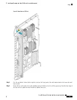
Step 4
Slide the card halfway into the slot. Avoid touching the card circuitry or any connectors.
Alignment grooves exist on each slot in the card cage. When you install a card in the card cage, make sure that
you align both edges of the card carrier in the slot grooves.
Note
Step 5
Pivot both card ejector levers so that the openings on the card ejector cams at the top and bottom of the card pass over
the tabs on each side of the card cage slot.
Verify that the openings on the card ejector cams pass over the tabs; otherwise, one or both ejector levers might
bind when you attempt to close the levers, thereby damaging or breaking one or both of them.
Caution
Step 6
Continue sliding the card into the card cage slot until the openings on the card ejector cams engage the tabs on each side
of the slot.
The LCC fan controller card has guide pins that make initial contact with the midplane connector as you slide
a card into its slot. After the guide pins make contact, continue pushing the card carrier until the card ejector
levers begin pivoting forward, toward the handle in the card carrier.
Note
Step 7
To seat the card in the midplane connector, grasp both card ejector levers and pivot them inward toward the handle in
the card carrier until they are flush against the front edge of the card carrier.
For easier installation, install both LCC fan controller cards before you tighten the fasteners.
Note
Step 8
Use the screwdriver to turn the two captive screws on the front panel of the LCC fan controller card clockwise to seat
the card firmly in the slot.
What to do next
After performing this task, place the impedance carrier in an antistatic bag for storage and future use. Close
the front (PLIM) side cosmetic doors and verify that the card has been installed properly (
Installation of an LCC Fan Controller Card, on page 143
). If you are performing the initial installation of the
system, install the route processors (
Installing an RP, PRP, or DRP Card, on page 146
) after you complete the
installation of the LCC fan controller cards.
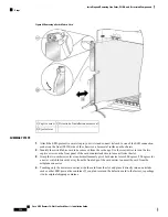
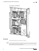
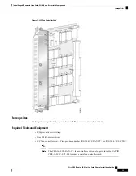
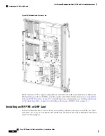
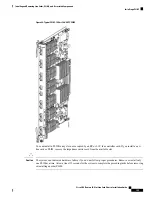
Removing an LCC Fan Controller Card
This section describes how to remove a fan controller card from the LCC. Two LCC fan controller cards,
shown in
Figure 75: LCC Fan Controller Card
, exist in every LCC.
Prerequisites
Before performing this task, open the front (PLIM) side cosmetic doors (if installed).
Required Tools and Equipment
You need the following tools to perform this task:
• ESD-preventive wrist strap
• Large Phillips screwdriver
Cisco CRS Routers 16-Slot Line Card Chassis Installation Guide
141
Installing and Removing Line Cards, PLIMs, and Associated Components
Removing an LCC Fan Controller Card


