


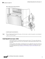


Step 10
Set the screws and strike tube carefully aside
Removing the Mid-chassis Horizontal Cable Management Bracket
Step 11
Remove the mid-chassis horizontal cable management bracket (as in the previous figure) by unscrewing the four flat
head Phillips screws (two for each side) that attach the bracket to the chassis.
Step 12
Set the screws and bracket carefully aside
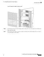
Removing the Rear Vertical Cable Troughs
Step 13
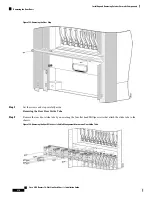
Remove the rear vertical cable troughs—one left and one right—from the rear of the chassis (see the next figure).
1.
Unscrew the 22 flat head Phillips screws (11 on each side) that attach it to the chassis (You might need to use a
ladder to reach the upper screws).
2.
Slide the cable troughs upward slightly to unhook them from the guide slots; lift them away from the chassis, and
set them carefully aside.
We recommend that you use two people to remove the troughs, one person to hold the troughs in place while
the other person removes the screws.
Note
Cisco CRS Routers 16-Slot Line Card Chassis Installation Guide
215
Installing and Removing Exterior Cosmetic Components
Removing the Rear Doors


