4-13
Cisco 6260 Hardware Installation Guide
OL-2365-02
Chapter 4 Installing a Cisco 6260 Without a POTS Splitter Configuration
Installation Procedures
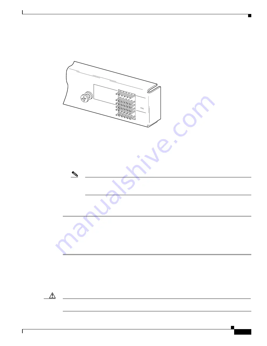
See
Figure 4-9
for a close-up of the pinouts that are located on the I/O module. For pinout
descriptions, see the
“E1 I/O Module RJ-48c Connectors” section on page C-2
.
Figure 4-9
I/O Module Wire-Wrap Pins Close-up
b.
Use a wire stripper to remove the casing from both ends of the wire.
c.
Use a wire-wrapping tool to attach the wire to the appropriate pin.
d.
Use a wire-wrapping tool to attach the other end of the wire that is used in Step 1c to either the BITS
clock source or alarm relay contact.
e.
Repeat this step to wire-wrap all the necessary pins.
Note
The BITS pins on Cisco 6260 I/O cards are slot specific. BITS_A pins are assigned to
chassis slot 11 and BITS_B pins are assigned to chassis slot 10. Each BITS clock input is
independent and terminated at 100 ohms.
Step 2
Reboot the system to reassociate the system MAC address.
Step 3
Repeat
Step 1
and
Step 2
for each Cisco 6260 chassis, as necessary.
4.2.9 Apply Power
Complete the following steps to apply power to the Cisco 6260 system:
Step 1
Apply power to the system with one of the following methods:
•
Install the fuses in the fuse and alarm panel.
•
Reinsert the fuses in the fuse and alarm panel, if you removed them in the
“Attach Cisco 6260 Power
Connections” section on page 4-9
.
•
Turn on the breakers in the fuse and alarm panel.
Caution
If the power connections are improperly made and power is applied while the cards are installed, the
cards and chassis could be damaged.
44750
PEM 1/PEM 2
AUD_CRIT/AUD_MAJ
AUD_MIN/VIS_CRIT
VIS_MAJ/VIS_MIN
STAT_ALARMS
BITS_A/BITS_B
60V
0.5 A MAX
LOGIC
INPUTS
BITS
CLO
CK


