INSTALLATION & SETUP
Roadster/Mirage S+ User’s Manual
2-27
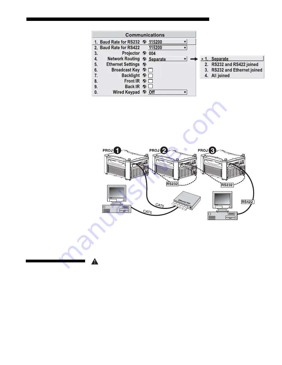
Figure 2.36. Keeping Communications Separate (default)
To relay all messages to all ports—RS232, RS422, and Ethernet—set the “Network
Routing” option in the
Communications
menu for each projector to “All Joined”.
This configuration is useful if you are using a non-RS232 controller with the RS232
linking available between these projectors. For example, you may want to use both an
RS422-compatible controller and an Ethernet-connected PC for working with a
network of projectors linked via their RS232 in/out ports (Figure 2.37).
Figure 2.37. Joining All Networks
To isolate just RS422 communications, select “RS232 and Ethernet Joined”. In
Figure 2.37, only projector #3 will respond to the RS422 controller. To isolate just
Ethernet communications, select “RS232 and RS422 Joined”—only projector #1 will
respond via Ethernet.
The North American rated line cord is provided with each projector. Ensure
that you are using a line cord that meets the appropriate rating standards (CCC
for use in China, PSE for use in Japan).
Plug the projector’s high-current line cord into the line input socket located in the
lower right corner of the rear panel of the projector, then plug the 3-pronged end of
the line cord into a grounded AC outlet. Make sure the socket outlet is installed near
the equipment and is easily accessible. Input voltage to
all Roadster and Mirage S+
models must be capable of
200
–
240
VAC.
Use the proper power source and the
high-current rated line cord provided.
See
Section 6, Specifications
for all power
requirements.
Communicating
to
'
All
Ports
2.7 Power
Connection
Summary of Contents for Mirage S+
Page 6: ......
Page 112: ......
Page 136: ......
Page 144: ......
Page 145: ...Appendix B Keypad Reference Roadster Mirage S User s Manual B 1 Figure B 1 Remote Keypad...
Page 148: ...SERIAL COMMUNICATION CABLES C 2 Roadster Mirage S User s Manual...
Page 158: ......


