CDE360 Vector Control AC Drive Chapter 6 Parameters Description
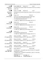
C1.22
Range: 0.0~600.0
Default: 0.0
Interval of Y1
output active
state
Unit: Sec
Define the digital output terminal Y1 output effective sate holdoff time..
C1.23
Range: 0.0~600.0
Default: 0.0
Interval of Y2
output active
state
Unit: Sec
Define the digital output terminal Y2 output effective sate holdoff time.
C1.24
Range: 0.0~600.0
Default: 0.0
Interval of T1
output active
state
Unit: Sec
Define the relay T1 output effective sate holdoff time.
C1.25
Range: 0.0~600.0
Default: 0.0
Interval of T2
output active
state
Unit: Sec
Define the relay T2 output effective sate holdoff time.
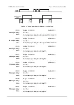
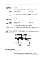
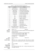
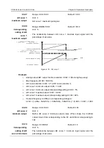
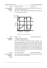
In some occasions, when the digital output terminal
s’ state is effective, hopes that the output
state of the terminal is time length adjustable, and not only a level signal. The holdoff time of
terminal’s effective state is only available after the output delay time.
Note:
When the holdoff time of terminal’s effective sate set to 0, equivalent cancel the
terminal’s effective state.
Delay
time
Internal
state
Actual output signal
after setting interval
of active state
Interval of
active state
High level effective
Signal
after delay
Delay
time
Delay
time
Delay
time
Interval of
active state
Figure 6- 14 The effective signal holdoff time of digital output terminal
Group C2: Analog Input
C2.00
Range: 0.00~10.00
Default: 0.10
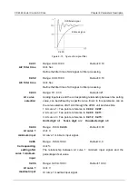
AI1 filter time
Unit: Sec
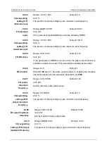
Define the filter time of analog input signal AI1, to filter processing.
Properly increasing this value can enhance the anti-interference ability of
analog input, but will weaken the sensitivity.


