CDE360 Vector Control AC Drive Chapter 6 Parameters Description
Group EA: External Brake
EA.00
①
Range: 0~1
Default: 0
External brake
enable
0: Inactive
1: Active
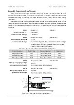
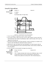
See the description of Figure below.
Output
frequency
Output
current
External
brake
control
Run
command
ON
EA.03
EA.02
EA.01
EA.04
EA.05
ON
EA.06 EA.07
OFF
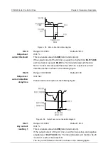
Figure 6- 51 External brake control schematic diagram
1. The AC drive begins to output when receives a start command.
2. If the output current is higher than EA.02 and the output frequency reaches EA.01,the Y
terminal allocated with function No.44"External brake control" becomes OFF when the
lasting time exceeds EA.03.
3. Then the AC drive keeps running at the frequency of EA.01,and begins to accelerate to set
frequency when the lasting time reaches the value set by EA.04.
4. When there is a stop command,the AC drive decelerates to run at the frequency of EA.05.
5. The Y terminal allocated with function No.44"External brake control" becomes ON after the
time set by EA.06.
6. The AC drive goes to stop mode after the delay time set by EA.07.
EA.01
①
Range: 0.00~10.00
Default: 2.50
External brake
off frequency
limit
Unit: Hz
The Y terminal allocated with function No.44"External brake control"
becomes OFF when the AC drive output frequency reaches EA.01.
Please set this parameter according to the motor rated slip frequency.


