


MV750i E, MV730i E, MV700i E, MV700 E, MV690 E
DISASSEMBLING
5
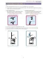
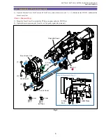
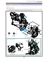
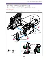
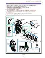
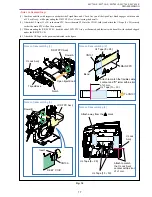
1-3 Separation of R-LCD Unit
(1) Open the LCD Unit and Cassette Cover, remove six screws (b
×
4, c
×
2), disconnect the CN102, and detach the R-LCD Unit.
Note : Use the new type connector (MAIN P.C.B., CN102) as illustrated.
Fig. 2
3mm
Metal
M1.7
Metal
M1.7
(self tap)
4.5mm
b
c
Note
Lock
Unlock
LCD Unit
Cassette Cover
R-LCD Unit
(1)
(1)
(1)
(1)
(1) - c
(1) - b
(1) - b
(1) - b
(1) - b
CN102
(1) - b
FPC
FPC
Metal
contact
Metal
contact
Summary of Contents for MV750i E
Page 193: ...22 MV750i E MV730i E MV700i E MV700 E MV690 E PARTS LIST Lens Unit Section 1 1 2 3 1 1 1 2 ...
Page 195: ...24 DMC III PARTS LIST 1 10 3 9 5 7 8 6 4 2 3 3 Mechanical Chassis Section 1 ...
Page 197: ...26 DMC III PARTS LIST 1 2 3 4 5 6 7 8 6 1 9 10 13 11 12 Mechanical Chassis Section 2 ...
Page 201: ...30 DMC III PARTS LIST 1 3 4 5 8 9 6 10 7 2 11 Mechanical Chassis Section 4 ...


