MV750i E, MV730i E, MV700i E, MV700 E, MV690 E
TECHNICAL DESCRIPTION
18
5-5 Error Detection
If an abnormality has been occurred in any rotation drive system (drum, capstan, reel, loading), a relevant mode enters. The LCD
indicates “PLEASE UNLOAD THE CASSETTE” and blinks “EJECT”.
5-5-1 Error Detecting Conditions
The following table gives error detecting conditions.
5-5-2 Processing after Error Detection
The following table gives processing after error detection.
• Pop up
: Error display
→
error eject
→
pop up
→
error clear
• Error stop
: Error display
→
STOP position (not cleared unless EJECTED)
Kind
Condition
Detection
Drum error
Error detecting mode
Starting / steady
D-FG
FG frequency when steady
900Hz
Error detecting level
Starting: Beyond 80-150%.
Steady : 30% max.
Error detecting time
Starting : 5sec.
Steady : 0.5sec.
Capstan error
Error detecting mode
Starting / steady
C-FG
FG frequency when steady
1347Hz
Error detecting level
Starting : 80% max.
Steady : 60Hz max.
Error detecting time
Starting : 2sec.
Steady : 2sec.
Reel error
Error detecting mode
Starting / Normal / UNLOAD
T, S-REEL FG
Error detection
Normally : The C-FG count per reel FG cycle is
C-FG
Starting : M ore than 3296
Steady : M ore than 2256
UNLOAD : Reel FG cycle is 1 sec or more
(Take-up reel only for both)
Loading error
Error detecting mode
M ode transfer
M ode SW
Error detection
M ode transfer time
STANDBY-STOP : 6sec
STANDBY-POPUP : 3sec
STOP-PLAY : 3sec
Cassette in
Loading
During
loading
Loading
completed
During tape
running
During mode
Drum error
Pop up
Pop up
Error stop
Error stop
Error stop
Error stop
Capstan error
Pop up
-------
Error stop
Error stop
Error stop
Error stop
Reel error
-------
-------
Error stop
Error stop
Error stop
Error stop
Loading error
Pop up
Pop up
Error stop
Error stop
-------
Error stop
Summary of Contents for MV750i E
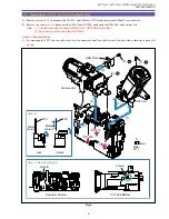
Page 193: ...22 MV750i E MV730i E MV700i E MV700 E MV690 E PARTS LIST Lens Unit Section 1 1 2 3 1 1 1 2 ...
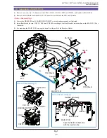
Page 195: ...24 DMC III PARTS LIST 1 10 3 9 5 7 8 6 4 2 3 3 Mechanical Chassis Section 1 ...
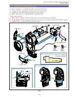
Page 197: ...26 DMC III PARTS LIST 1 2 3 4 5 6 7 8 6 1 9 10 13 11 12 Mechanical Chassis Section 2 ...
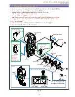
Page 201: ...30 DMC III PARTS LIST 1 3 4 5 8 9 6 10 7 2 11 Mechanical Chassis Section 4 ...


